Section 5 - 4-rank superweeder, Set-up instructions, Section 5 – Summers 4-Rank Superweeder User Manual
Page 83: Assembly & operation: 4-rank superweeder, Set-up instructions and parts -1 - 5-20
SECTION 5 - 4-RANK SUPERWEEDER
5-1
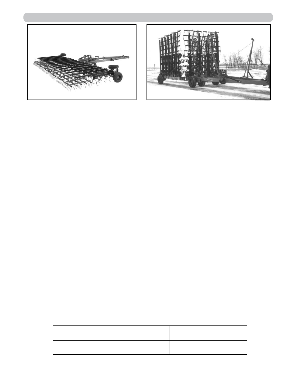
Fig. 1: Field Position
Fig. 2: Transport Position
The machine should be placed in an area that allows ample room for field position assembly (See
Fig. 1).
CAUTION: For safety purposes, block equipment while working on it.
Refer to illustrations and parts listings on pages 5-2 through 5-20 and follow these steps when as-
sembling.
HITCH – Axles, Wheels and Jack
Attach hitch axle assemblies as shown on page 5-2. Position center of axles 19” ahead of the rear
of the hitch 8” X 4” tube. Mount hitch wheels and tires and install hitch jack.
If machine is equipped with optional Hydraulic Depth Adjustment, attach hitch Hydraulic Depth Adjust-
ment and axle assemblies as shown on page 5-3. Mount hitch wheels and tires and install hitch jack.
DRAWBAR – Center, Hydraulic Lift Cylinders, Wings, Axles and Wheels.
Attach center drawbar to hitch using two 1-1/4” X 6” pins and secure with flat washers and 5/16” X
2-1/2” cotter pins. Mount main lift cylinders and transport locks. Route hoses as shown on page
5-14. Fully charge main lift cylinders with hydraulic fluid by extending and retracting until all air is
purged from system.
Knuckles are marked left and right. Before attaching wings, check that knuckles are on correct side
of machine. Attach wings to knuckles using 1-1/2” X 11” pins. Secure with 1/2” X 2-1/2” bolt, washer
and locknut. Install 1-1/2” jam nuts, center punch or spot weld to secure. Attach jack mounting swivels
on top of wing near knuckle in field position. Secure with 7/8” u-bolt, lockwashers and nuts.
Mount wing axle plates with spindle down as shown on page 5-5 or wing Hydraulic Depth Adjustment
Option assemblies (page 5-3). Mount wing wheels and tires. Do not mount transport wheel assem-
blies until lift arms are positioned.
LIFT ARMS: 4-RANK SUPERWEEDER
Refer to Figures 3 and 4 and parts pages 5-8 thru 5-11. All lift arms are spaced 30” center to center.
Attach lift arms to drawbar using 7/8” u-bolts and hardware provided. See chart below for lift arm
settings.
NOTE: Special lift arms are used where hydraulic cylinders are located.
Max. Tillage Depth Lift Arm Setting Hole Tube Bushing Setting Hole
2”
Upper
Upper
3-1/2”
Upper
Lower
5”
Lower
Lower