Section assembly – Summers 4-Rank Superweeder User Manual
Page 22
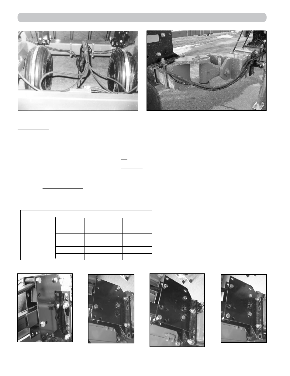
Fig. 3: Rear Hitch View
Fig. 3A: Left Knuckle
SECTIONS:
Attach sections to drawbar using 7/8” U-bolts and hardware provided. Position lift arms with follow-
ing dimensions:
Distance from drawbar center to centerline of first lift arm on either side is 24”.
Distance between centerlines of lift arms on sections is 24”.
Distance between centerlines of lift arms between sections is 48”.
To compensate for various soil conditions and tooth wear, the sections can be mounted in four dif-
ferent positions as shown in the following chart and (Fig. 4 to 7). On the center two sections only,
move the Lower Stop Bolt and bushing to the front hole (Fig. 8). This will allow the sections to raise
more evenly.
Height Adjustment
Suggested
Initial
Setting
U-Bolt
Plate
Up
Down
Up
Down
Lift Arm/
Spring Flat
Up
Up
Down
Down
Ref.
Fig. 4
Fig. 5
Fig. 6
Fig. 7
Fig. 4
Fig. 5
Fig. 6
Fig. 7
– Initial Setting
– Settings for increased
– penetration and/or to
– compensate for harrow tooth wear
SECTION 2 - SUPERHARROW PLUS
2-10