Section 4 - harrow packer, Set-up instructions, Section 4 – Summers 4-Rank Superweeder User Manual
Page 67: Assembly & operation: harrow packer
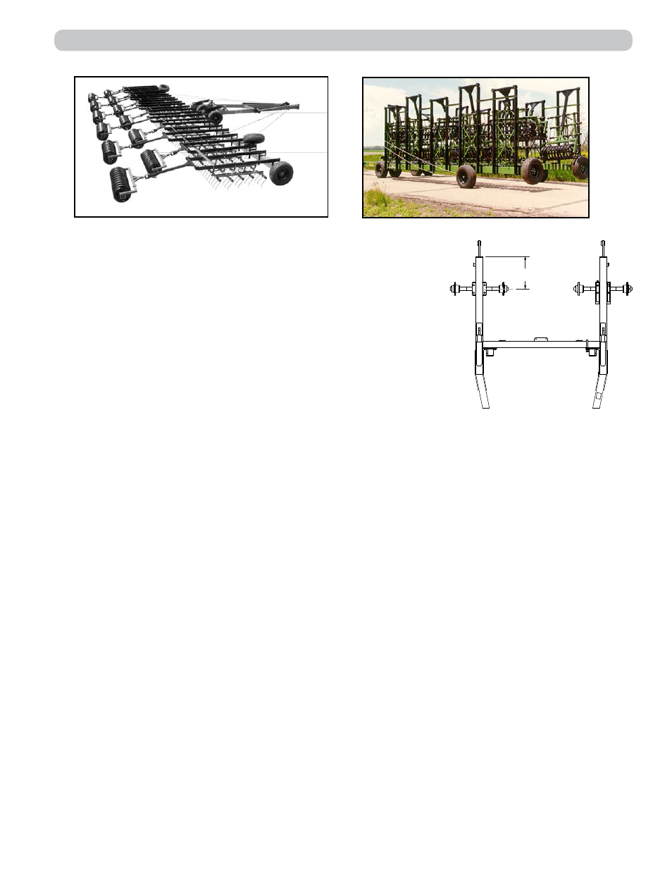
19"
19”
SECTION 4 - HARROW PACKER
4-1
SET-UP INSTRUCTIONS
Fig. 1: Field Position
Fig. 2: Transport Position
The machine should be placed in an area that allows ample room
for field position assembly (See Fig. 1).
Refer to illustrations and parts listings in this section. Position center
of axles 19” ahead of the rear of the hitch 8” X 4” tube. Mount hitch
wheels and tires and install hitch jack. If machine is equipped with
optional Hydraulic Depth Adjustment, see pages 3-3 through 3-7
for (HDA) assembly.
DRAWBAR – Center, Hydraulic Lift Cylinders, Wings, Axles
and Wheels.
Attach center drawbar to hitch using two 1-1/4” X 6” pins and secure
with flat washers and 5/16” X 2-1/2” cotter pins. Mount main lift
cylinders and transport locks. Route hoses as shown on page 4-6. Fully charge main lift cylinders
with hydraulic fluid by extending and retracting until all air is purged from system.
Knuckles may be marked left and right. Before attaching wings, check that knuckles are on correct
side of machine. Attach wings to knuckles using 1-1/2” X 11” pins. Secure with 1/2” x 2-1/2” bolt, flat
washer and lock nut. Install 1-1/2” jam nuts, center punch or spot weld to secure. Attach jack mounting
swivels on top of wing near knuckle in field position. Secure with 7/8” u-bolt, lockwashers and nuts.
Mount wing axle plate with spindle down. Mount wing wheels and tires. Do not mount transport wheel
assemblies until lift arms are positioned.
HYDRAULIC SYSTEMS
Mount Auto-Fold lock, cylinder and hoses shown on page 4-6.
NOTE: The tractor hydraulic control valve operating auto-fold lock cylinder must hold pressure. If
auto-fold lock cylinder extends during field operation, damage will occur.
LIFT ARMS AND SECTIONS
Sections with 3/8” diameter teeth:
Attach lift arms to drawbar using 3/4” X 10” cap screws. Position lift arms with following dimensions:
Distance from drawbar center to centerline of first lift arm on either side is 15”.
Distance from centerline of lift arms over sections is 30”.
Distance between centerline of lift arms between sections is 30”.
Use two long lift arms for first section to left of center. Lift arms for adjoining sections must be alter-
nating lengths (short and long).
Assemble sections as shown in parts breakdown on page 4-9. Attach sections to lift arms with chains
and hardware provided. The 9-link lift chain must be attached to the back hole in both lift arm and
section. Mount OPTIONAL SPRING PRESSURE in front hole in both lift arm and section. Spring
pressure rod must not lift harrow section into transport position. Use 8 of 9 chain links to insure that
chain lifts section.