Transport wheels, Auto-cable fold, Cables – Summers 4-Rank Superweeder User Manual
Page 55
SECTION 3 - SUPERHARROW 2650
3-11
The two front teeth on the wing (closest to knuckles) must be secured
with PN 8HD6150 (ANGLE, tooth stop) and 1/2” X 3-3/4” cap screws as
shown in Fig. 9. This prevents interference in transport position.
TRANSPORT WHEELS
Locate transport wheel assemblies over end harrow section on 56 ft. ma-
chine with pivot tube in higher position. Install between end section and
second section on 72 ft. and 88 ft., both with pivot tube in lower position.
Secure with 7/8” U-bolts and hardware.
Transport axle “toe-in” can be adjusted with the outside stop set bolt
(8X0665, Page 3-5). Adjust inside stop bolt 3/8” away from pivot plate
when resting on outside stop bolt. This adjustment will allow transport
wheel to pivot inward while unfolding. Double lock stop bolts with 3/4”
jam nuts provided.
AUTO-CABLE FOLD
Mount Auto-Fold pivot brackets ahead of welded stop. Do not fully tighten
U-bolts. Attach left and right cable fold arms to pivot brackets with 1-1/4”
X 14” pins and hardware.
Adjust pivot brackets to provide clearance between the cable fold arm
bottom guide and hitch tube. This adjustment is made with 3/4” X 2-1/4”
bolts (8X0112, Page 3-7). This adjustment will allow cable fold arms to pivot freely into transport position. Fully tighten
mounting U-bolts after adjustment is made.
Attach tension springs with 3/4” eye bolts and lock nuts. Tighten eye bolts until spring coils begin to separate.
CABLES
Install cable brackets and cable assemblies. Adjust cables so wings lead the center by 2 degrees. Tighten attachment
U-bolt. Recheck tightness after first hour of field use. Install rear cables as shown on page 3-13 through 3-15. 72’ and 88’
SuperHarrow 2650 ONLY: Install Cable Guides as shown on next page.
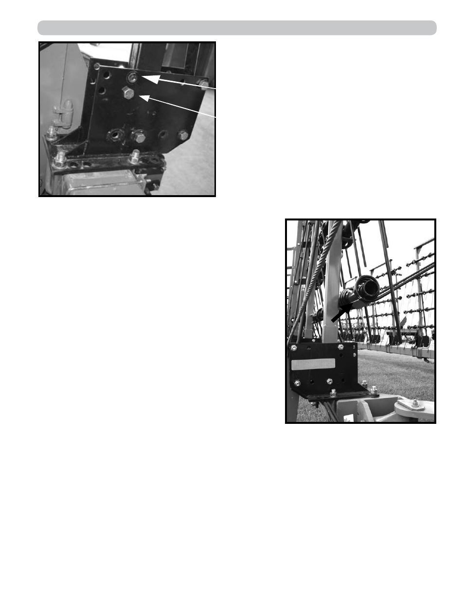
Wing Section Lower Stop Bolt Location
Center Section Stop Bolt Location
(shown installed)
Fig. 8
Fig. 9: ANGLE, tooth stop