Chapter 3: wiring, 1 wiring connections, Power supply/ground connections – AMETEK 957 SSI Brik User Manual
Page 7: Cable connectors
7
1080 N. Crooks Road • Clawson, MI 48017 • 800.635.0289 • Phone 248.435.0700 • Fax 248.435.8120 • www.ametekapt.com
FACTORY AUTOMATION
®
Chapter 3: Wiring
Once the LDT has been installed, wiring connections can
be made. There are two groups of connections you will
need to make. They are as follows:
• Power Supply Connections (including ground and
shield)
• LDT Input/Output Connections
Power Supply/Ground Connections
The 957SSI is available with many different connector/wir-
ing options. Refer to part numbering on unit in question
for proper wiring. See Section 3.5 for part numbering and
figures 3.3 - 3.8 for wiring details.
The 957SSI standard cable is a 6 Pin, 12mm, cordset.
It has 6 conductors of 24ga, with an aluminum/poly-
ester/aluminum foil with drain wire plus an over-
all braid of tinned copper shield. Cable O.D. is .23
(5.7mm ). To reduce electrical noise, the shield must be
properly used. Connect the cable’s shield to the controller
system GND.
Always observe proper grounding techniques such as sin-
gle point grounding and isolating high voltage (i.e. 120/240
VAC) from low voltage (7-30 VDC cables). Whenever pos-
sible, this cable should be run in conduit by itself. The
power supply common, the cable shield and a good earth
ground should be connected together at the location of
the power supply common. See figure 3-1 Power Supply
Wiring.
WARNING Do not route the Brik™
output cable near high voltage
sources.
3.1 Wiring Connections
UNIPOLAR
Single ended
power supply
+7 to +30 VDC
+ COM
Power+
Common
Figure 3-1 Power Supply Wiring
In order for the 957SSI to operate properly, the LDT’s ex-
ternal power supply must provide a voltage between +7
to +30 VDC. The power supply must be rated at 150mA
minimum. The power supply should provide less than 1%
ripple and 10% regulations. (The power supply should be
dedicated to the LDT to prevent noise from external loads
from affecting the position readings.)
Cable lengths
AMETEK recommends that the maximum cable length be
10 meters. Cables greater than 33 feet are available; how-
ever, proper care must be taken during installation.
Any extension to the existing cabling should be mount-
ed in a junction box free of any other cabling, the cable
should be a twisted shielded pair with a braided shield.
The shield should pass straight thru this enclosure and not
tied to ground. When grounding the LDT, a single earth
ground should be connected to the power supply common.
The LDT power supply common should be connected to
the power supply common (-) terminal. The LDT’s shield
should be tied to the earth ground at the power supply.
Cable length limitations are based on SSI clock fre-
quencies. Apply good industry practices for long cable
runs - keep cable away from high power AC lines and all
motor drive cables.
Cable Connectors
The 975SSI is available with various cable connection op-
tions. See figure 3-2 for standard options. Should a differ-
ent connector be required for an application, please con-
tact the factory at 800-635-0289.
!
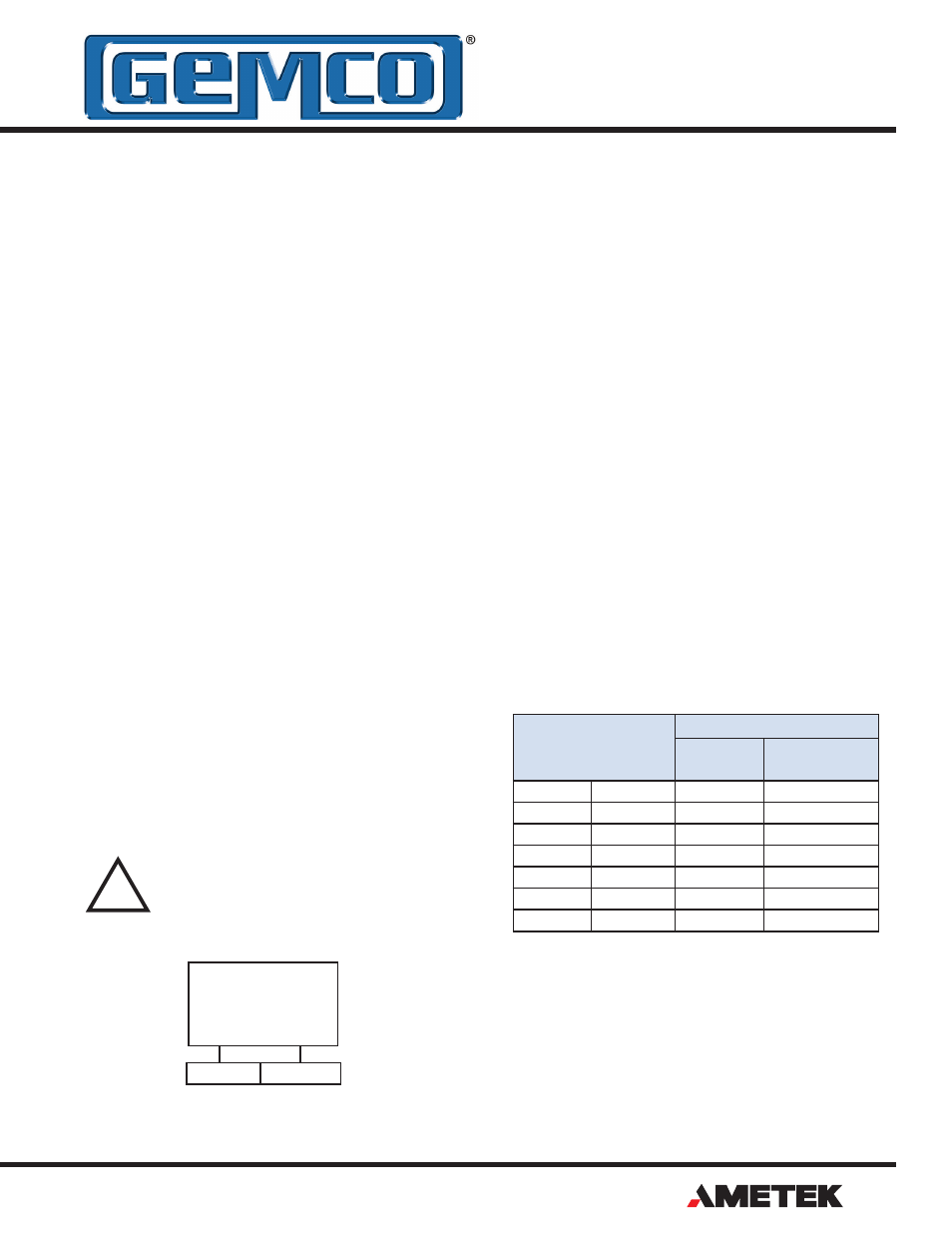
Note: Minimum SSI clock frequency rate is 70 kHz.
Cable Length
Controller Data Sampling
Falling
Edge
Rising Edge
6 ft
1.83 m
750 kHz
1500 kHz
30 ft
9.14 m
650 kHz
1300 kHz
100 ft
30.48 m
500 kHz
1000 kHz
150 ft
45.72 m
400 kHz
800 kHz
300 ft
91.44 m
270 kHz
540 kHz
600 ft
182.88 m
160 kHz
320 kHz
1200 ft
365.76 m
90 kHz
180 kHz