AMETEK 957 SSI Brik User Manual
Page 3
3
1080 N. Crooks Road • Clawson, MI 48017 • 800.635.0289 • Phone 248.435.0700 • Fax 248.435.8120 • www.ametekapt.com
FACTORY AUTOMATION
®
SSI Clock (+)
SSI Clock (-)
Ω
µ
SSI Data (+)
SSI Data (-)
+7 to 30 V
0V
Input
Power
Supply
SSI Shift Register and Controller
Output Data Format Conversion
Position Measurement
SSI Clock (+)
SSI Clock (-)
4.7KΩ
470Ω
4.7KΩ
12V
12V
10Ω
10Ω
Ω
µ
SSI Data (+)
SSI Data (-)
12V
12V
10Ω
10Ω
Power Supply (+)
Common
33V
Input
Power
Supply
Ferrite
Filter
+5V
RS-422
RS-422
Clock (+)
Data (+)
Clock Interval
LSB
MSB
Min. 16 µs
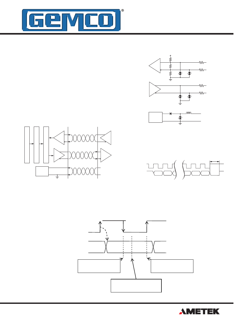
SSI Logic Diagram
SSI Sensor Input
SSI Timing Diagram
SSI (Serial Synchronous Interface)
The displacement value (position) is encoded into a 24, 25
or 26 Bit format and transmitted at high speeds. Synchroni-
zation in a closed loop system is made easy. A clock pulse
train from a controller is used to shift out sensor data: one
bit of position data is transmitted to the controller for one
clock pulse received by the sensor. The absolute position
data is continually updated by the sensor and converted
by the shift register into serial information.
CLOCK
DATA
SAMPLING AT
FALLING EDGE
SAMPLING AT
RISING EDGE
SAMPLING
BETWEEN EDGES
Note: Based on Gemco cable P/N 01533149 (Turck P/N RF50610-30M).
New data is placed on the "data" signal 605nS after the rising edge of the "clock" signal. This time, plus the data caused
by cable length, must be considered when determining the setup times (frequency) of the controller.