2 requirements at the place of installation, 3 installation instructions concerning actuators – ARI Armaturen STEVI 451 EN User Manual
Page 8
Page 8
Rev. 0040306000 0410
Operating and installation instructions
3-way control valves - STEVI
®
450 / 451
5.2 Requirements at the place of installation
The place of installation should be easily accessible and provide ample space for
maintenance and removing the actuator. Stop valves should be installed before and behind
the control valve to enable maintenance working without draining the piping system. The
valve should preferably installed vertically with the actuator at the top. Inclined or horizontal
installation without supports is permissible only with light actuators.
For this installation position, the two distance columns (or joke) have to be above each
other in the vertical plane.
Safe actuator weights for a horizontal installation position with reference to the stem,
without structural support, are as follows:
20 kg for DN 15 - 32
25 kg for DN 40 - 65
35 kg for DN 80-100
40 kg for DN125-150
55 kg for DN125v-150v
The pipes must be lagged to protect the actuators from excessive heat. Sufficient space
must be left for the maintenance of the stem packing.
To ensure that the control valves function correctly, the pipe run should be straight for at
least 2 x DN upstream and 6 x DN downstream of the valve.
5.3 Installation instructions concerning actuators
Normally, control valves are supplied complete with actuator fitted.
It is not permitted to mantle / dismantle actuators with valves operating at service conditions
(temperature and pressure) the actuators must be assembled as describe in the operating
instructions during conversion and maintenance.
During assembly work, the plug is not be turned on its seatring at closing pressure.
When retrofitting actuators, the maximum permissible force for valve actuation must be
taken into account:
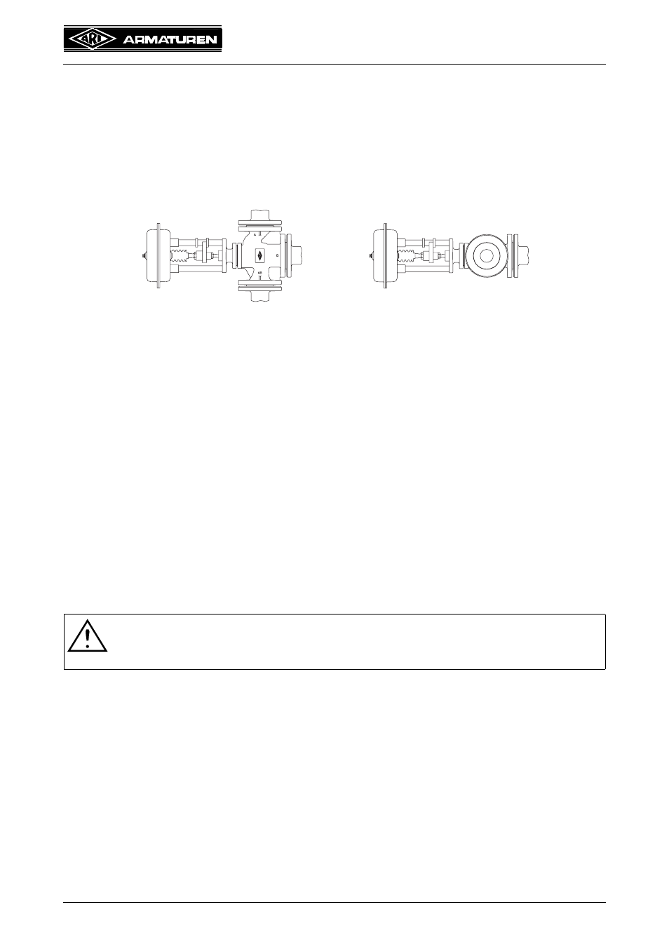
Fig. 10: Pipeline vertically
Fig. 11: Pipeline horizontally
ATTENTION !
Care must be taken with the bellow type valves when actuators are mounted or
removed. (Hold the valve-stem against turning with an open-end wrench!)
Series 450
Series 451
12 kN for DN 15- 50
18 kN for DN 15-100
29 kN for DN 65-100
37 kN for DN125-150 / 125v-150v
40 kN for DN125-150
59 kN for DN125v-150v