2 bellows seal and diverting plug – ARI Armaturen STEVI 451 EN User Manual
Page 13
Rev. 0040306000 0410
Page 13
Operating and installation instructions
3-way control valves - STEVI
®
450 / 451
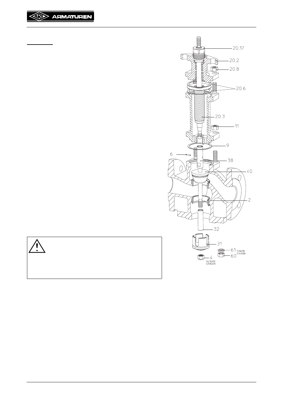
7.1.3.2 Bellows seal and diverting plug
DN40-150
- Dismantle as item 7.1.3.
- Pull distance bush (pos. 32) from adapter (pos. 38).
Note:
There is no distance bush (pos. 32) on DN 125-150.
- Loose nuts (pos. 11).
- Detach bellows assembly (pos. 20).
- DN 15-100: Pull plug (pos. 40) from adapter
(pos. 38).
- DN 125-150: Drive straight pin (pos. 33) out with a
drift. Screw plug (pos. 40) from adapter (pos. 38).
- Loose nuts (pos. 20.8).
- Detach mounting bonnet (pos. 20.2).
- Extract stem-/bellows unit (pos. 20.3) from the
bellows housing (pos. 20.1).
- Drive pin (pos. 6) out with a drift.
- Unscrew stem adapter (pos. 38).
Note:
Adapter (pos. 38) and straight pin (pos. 6) are not
existing at DN40-50.
- Bolt new parts together, drill and pin them.
- Replace 2 gaskets (pos. 20.6) and 1 gasket
(pos. 9).
- Assemble in reverse order
.
(For tightening torques refer to item 7.3.)
- Secure with nuts (pos. 11 and 20.8) and tighten
them crosswise.
(For tightening torques refer to item 7.3.)
- Tighten screw joint (pos. 20.17) gradually up to tightness of the stuffing box packing
(pos. 20.10).
ATTENTION at DN125-150!
- Ensure that the torsion lock is correctly
positioned when inserting new stem/
bellows unit. Introduce the straight pin
(pos. 20.9) into the torsion lock groove.
Make sure it runs smoothly!
Fig. 18:
Series 451 DN15-150
with diverting plug