Controller power connections, Input connections, Control and alarm output connections – Red Lion PXU User Manual
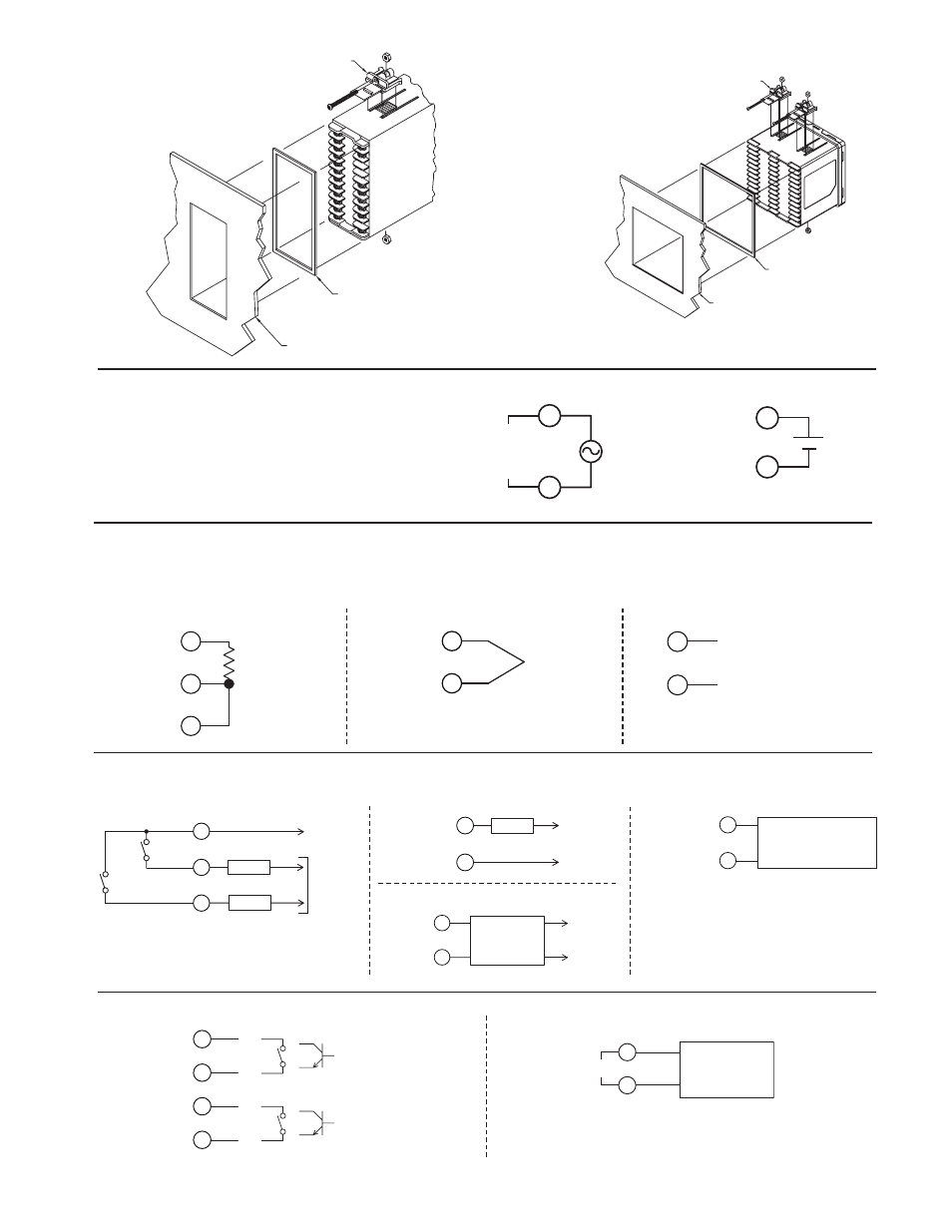
Page 3: 1/8 din installation, 1/4 din installation
3
CONTROLLER POWER CONNECTIONS
For best results, the power should be relatively “clean” and within
the specified limits. Drawing power from heavily loaded circuits or
from circuits that also power loads that cycle on and off should be
avoided. It is recommended that power supplied to the controller be
protected by a fuse or circuit breaker.
2
1
L
N
AC 100-240V
50/60 Hz
5VA
INPUT CONNECTIONS
For two wire RTDs, install a copper sense lead of the same gauge and length
as the RTD leads. Attach one end of the wire at the probe and the other end to
input common terminal. This is the preferred method as it provides complete
lead wire compensation. If a sense wire is not used, then use a jumper. A
temperature offset error will exist. The error may be compensated by
programming a temperature offset.
12
11
10
TC-
TC+
12
11
DC+ VOLTAGE/CURRENT
DC- VOLTAGE/CURRENT
12
11
CONTROL AND ALARM OUTPUT CONNECTIONS
VAC
RTD and Resistance
Thermocouple and Millivolt
Voltage and Current
LOAD
AC/DC
Power (-)
LOAD
COMM
NO
NO
AC/DC
Power (+)
AL 2
AL 1
AC/DC
Power
LOAD
COMM (-)
NO (+)
AC Power
SSR
COMM (-)
NO (+)
POWER
UNIT
+
-
AC
AC
Alarm 1 and 2 * (1/16 DIN Shown)
OP1/OP2 Output Control Relay *
OP1 Output Control Logic/SSR *
USER INPUT CONNECTIONS *
User 1
+
User 2
+
-
-
* See unit label for terminal identification.
RS 485 CONNECTIONS *
D+
D-
RS485
RECEIVING
DEVICE
+
-
RS-485
1/8 DIN Installation
20
24
23
22
21
14
17
19
18
15
16
13
(2) PANEL LATCH
(SUPPLIED W/UNIT)
PANEL
GASKET
EXISTING PANEL CUT-OUT
1.76" (44.5 mm) X 3.60" (91.5 mm)
(4) PANEL LATCH
(SUPPLIED W/UNIT)
PANEL
GASKET
EXISTING PANEL CUT-OUT
3.58" (91.0 mm) X 3.58" (91.0 mm)
1/4 DIN Installation
0 V
DC 24V
2
1
+
_
VDC
ANALOG INPUT
CONTROL
DEVICE
COMM (-)
NO (+)
IN +
IN -
OP1 Output Control Analog *