Installing the controller, Dimensions in inches (mm) - 1/4 din, Dimensions in inches (mm) - 1/8 din – Red Lion PXU User Manual
Page 2: Setting the current input jumper, Safety summary, 1/16 din installation, Instructions, Thermocouple, rtd or voltage input, Factory setting
2
INSTALLING THE CONTROLLER
The controller is designed to be mounted into an enclosed panel. The unit
must be inserted in the case during installation of the controller.
Instructions:
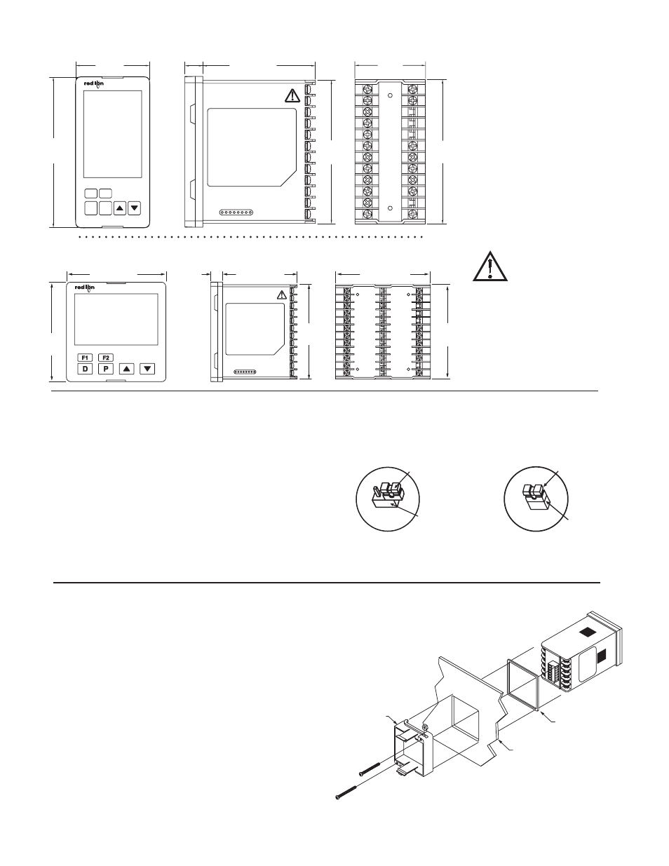
1. Prepare the panel cutout to the proper dimensions.
2. Assemble the mounting clip by inserting the nut into the slot and then insert
the screw and thread through the nut as shown (See drawing)
3. Slide the panel gasket over the rear of the controller, seating it against the lip
at the front of the case.
4. Insert the controller into the panel cutout. While holding the controller
in place, install the panel latch(es) and then slide it to the farthest
forward slot possible.
5. To achieve a proper seal, tighten the panel latch screws evenly until the
controller is snug in the panel, torquing the screws to 13.9 to 20.8 oz-in
(9.8 to 14.7 N-cm). Overtightening can result in distortion of the
controller, and reduce the effectiveness of the seal.
Note: The installation location of the controller is important. Be sure to
keep it away from heat sources (ovens, furnaces, etc.) and away from
direct contact with caustic vapors, oils, steam, or any other process
by-products in which exposure may affect proper operation.
3.77
(95.8)
3.77 (95.8)
0.45
(11.4)
2.82 (71.5)
3.58 (91.0)
3.58
(91.0)
3.58
(91.0)
24
22
21
20
19
18
17
16
15
14
13
12
10
9
8
6
7
5
4
3
1
2
11
23
36
35
34
33
32
31
30
29
28
27
26
25
DIMENSIONS In inches (mm) - 1/4 DIN
13
14
16
15
18
17
19
20
21
22
23
24
1
2
3
4
5
6
7
11
10
9
8
12
3.77
(95.8)
(11.4)
0.45
2.82 (71.5)
(44.5)
1.76
(91.5)
3.60
3.60
(91.5)
(48.0)
1.89
F1 F2
D
P
DIMENSIONS In inches (mm) - 1/8 DIN
PANEL CUT-OUT
PANEL CUT-OUT
SETTING THE CURRENT INPUT JUMPER
When Input Type is selected as one of the two current input types (0-20 or
4-20), the current input jumper must be installed. The current input jumper is
factory set for Temperature and Voltage input types. To change the jumper to
configure the input for a current input type, the inside of the unit must be
accessed and the jumper position changed.
To access the jumper, locate the two latches located on top and bottom of the
front of the unit. Starting with the top latch, insert a small flat-blade screwdriver
between the case latch and bezel while using your thumb to push out on the
bezel until the latch is disengaged. Repeat this process with the bottom latch.
After the latches are disengaged, using the flat-blade screwdriver, gently pry out
on the bezel in several areas until the unit releases from the case.
Look for the Current Input Jumper which will be located close to the pc board
area that connects to the input terminals. If a current input type is desired,
position the jumper across both pins. If input type is anything other than a
current input, position the jumper on only one pin.
CAUTION: Risk of Danger.
Read complete instructions prior to
installation and operation of the unit.
SAFETY SUMMARY
All safety related regulations, local
codes and instructions that appear in the
manual or on equipment must be observed
to ensure personal safety and to prevent
damage to either the instrument or
equipment connected to it. If equipment is
used in a manner not specified by the
manufacturer, the protection provided by
the equipment may be impaired.
Do not use the controller to directly
command motors, valves, or other
actuators not equipped with safeguards. To
do so can be potentially harmful to persons
or equipment in the event of a fault to the
controller. If redundant safeguards are not
in place, an independent and redundant
temperature limit indicator with alarm
outputs is strongly recommended.
JUMPER
PIN HEADER
JP8
FACTORY SETTING
Thermocouple, RTD
or Voltage Input
JUMPER
PIN HEADER
JP8
Current Input
(4-20 mA or 0-20 mA)
7
8
9
10
11
12
PANEL LATCH
(SUPPLIED W/UNIT)
EXISTING PANEL CUT-OUT
1/16 DIN
1.77” (45.0 mm) X 1.77” (45.0 mm)
PANEL GASKET
1/16 DIN Installation