Ordering information, Leds, Configuration – Red Lion CSRTD6 User Manual
Page 6: Sts – status led, Startup routine firmware upgrade, Error states alm – alarm led
6
ORDERING INFORMATION
Note: Certain modules are not suitable for use in Hazardous locations. Check each module’s specifications prior to installation.
1
Visit www.redlion.net for a complete list of PID modules, data acquisition modules, communications drivers and cables.
2
Free at www.redlion.net
Programming Cable for CS, G3, & Paradigm Series
Crimson
®
Programming Software
2
Communications Cables
1
Crimson
®
Programming Software, Manual, and Download Cable
Rail Stops (Qty 2)
Replacement Base
Replacement Termination Plug
CBL
Communications
Cables
(10 feet)
Software
Accessories
CBLPROG0
SFCRM
CBLxxxxx
SFCRK
RSRSTP00
CSBASE00
CSTERM00
8 Channel ±10 V Input Module, 100-Point Linearizer
6 Channel RTD Module
CSINV8L0
CSRTD600
8 Channel ±10 V Input Module
8 Channel 0(4)-20 mA Input Module, 100-Point Linearizer
8 Channel 0(4)-20 mA Input Module
8 Channel Thermocouple Module
CSINV800
CSINI8L0
CSINI800
CSTC8000
CSINI
CSTC
1
CSINV
CSRTD
Input Modules
Modular Controller Master, Multi Comms ports and Ethernet
CSMSTR
Master Module
CSMSTRGT
CSMSTRSX
CSMSTRV2
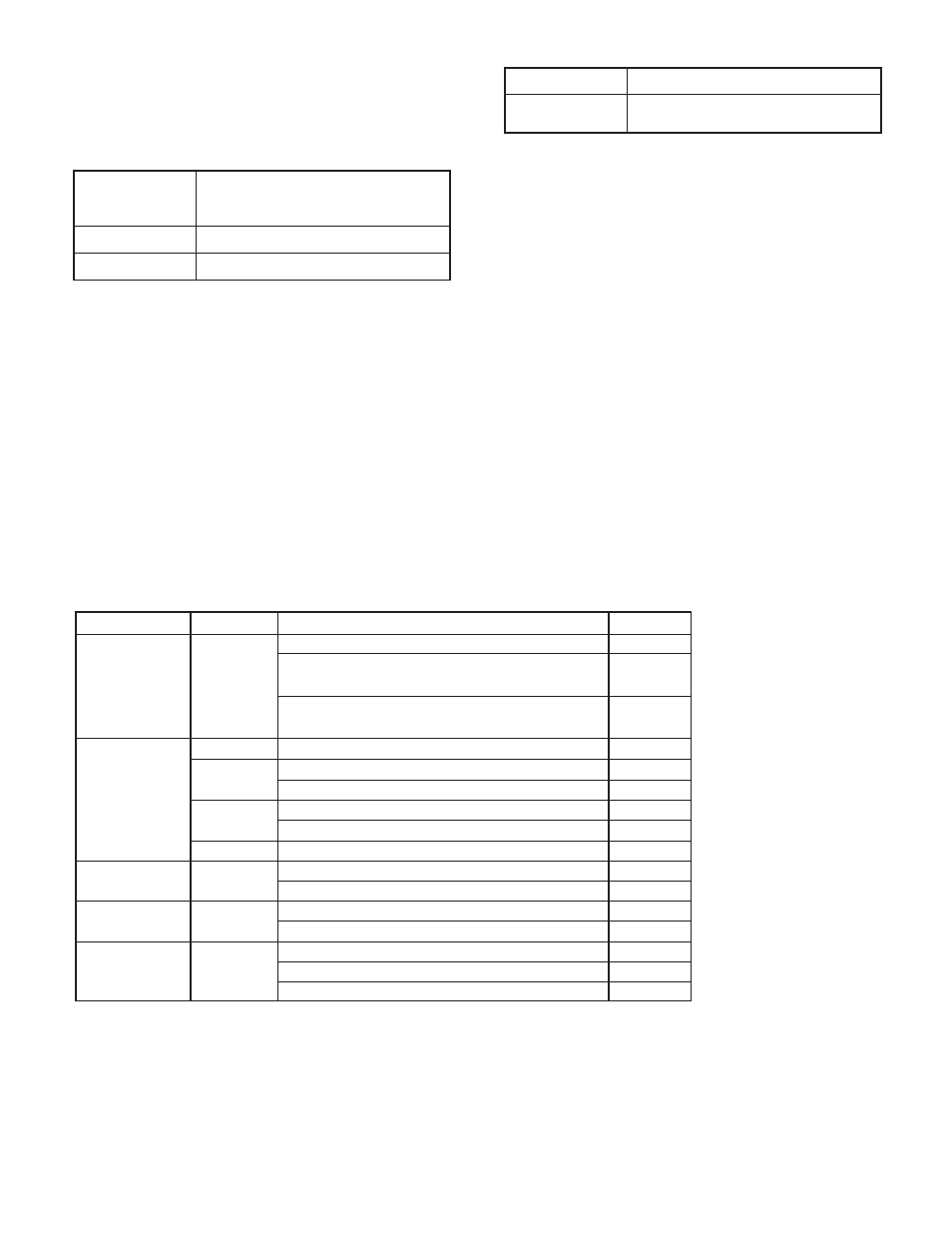
DESCRIPTION
MODEL NO.
TYPE
PART NUMBER
Modular Controller Master with multiple protocol converter, data
logger, web server with Virtual HMI up to QVGA (320 x 240) size
and expansion slot.
Modular Controller Master with multiple protocol converter, data
logger, web server with Virtual HMI up to VGA (640 x 480) size
and expansion slot with increased SDRAM
LEDS
STS – STATUS LED
The Status LED is a dual color LED that provides information regarding the
state of the module. This includes indication of the various stages of the start-up
routine (power-up), as well as any errors that may occur.
Startup Routine
FIRMWARE UPGRADE
The module's firmware is stored in flash memory so that software/hardware
conflicts are avoided, and so that software features may be added in the future.
During a download, Crimson compares its own library of firmware files with
those stored in the Master module. If they do not match, Crimson will download
the necessary files. The Master then checks to make sure that the I/O modules
contain the same firmware. If they contain a different revision, the Master will
automatically copy those files into the module's flash memory. During this
process, the module LEDs will flash rapidly, starting with the top row, and
progressing through the remaining rows until the process is complete.
Error States
ALM – ALARM LED
The Alarm LED indicates the presence of an input fault condition. When one
or more Input Fault Alarm bits is high, the LED turns on. The alarms may be
disabled for unused inputs.
CONFIGURATION
Programming is done via Crimson
®
software, a Windows
®
compatible
configuration interface. Please see the Crimson manual for more information.
Rapidly Flashing Red
Module is currently running the boot loader and/
or being flash upgraded by Crimson. This occurs
for four seconds during a power up.
Steady Red
Module switching to configuration.
Green
Module performing normally.
Module is controlling properly, but has lost
communication with the Master.
Green/Pulsing Red
Module not controlling, and not communicating.
Solid Red