Figure 7, I/o connectors, Table 1 – Vaisala WAC155 User Manual
Page 20: Anemometer connector (x1) pinout
User's Guide ______________________________________________________________________
18 ___________________________________________________________________M210822EN-A
0702-008
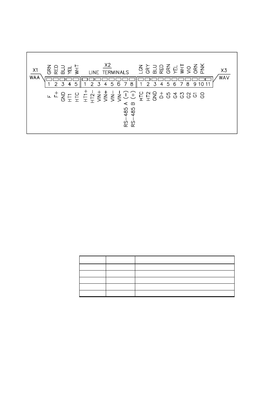
Figure 7
I/O Connectors
I/O connector X1-X3 pinouts are shown in following tables.
The following numbers refer to
X1 =
Plug-in connector with screw terminals (5 pcs) for the
anemometer cable. Maximum wire cross section area is 1.5
mm
2
.
X2 =
Plug-in connector with screw terminals (8 pcs) for the power
and signal cable. Maximum wire cross section area is 1.5
mm
2
.
X3 =
Plug-in connector with screw terminals (11 pcs) for the wind
vane cable. Maximum wire cross section area is 1.5 mm
2
.
Table 1
Anemometer Connector (X1) Pinout
Pin #
Signal
Description
1
F
Pulse input from sensor
2
F+
Supply voltage output to sensor
3
GND
Sensor ground
4
HT1
Heating supply-1 from connector X2
5
HTC
Heating common for heater serial connection