Relays – Vaisala GMT220 User Manual
Page 17
Chapter 3 _______________________________________________________________ Installation
VAISALA _______________________________________________________________________ 17
0807-038
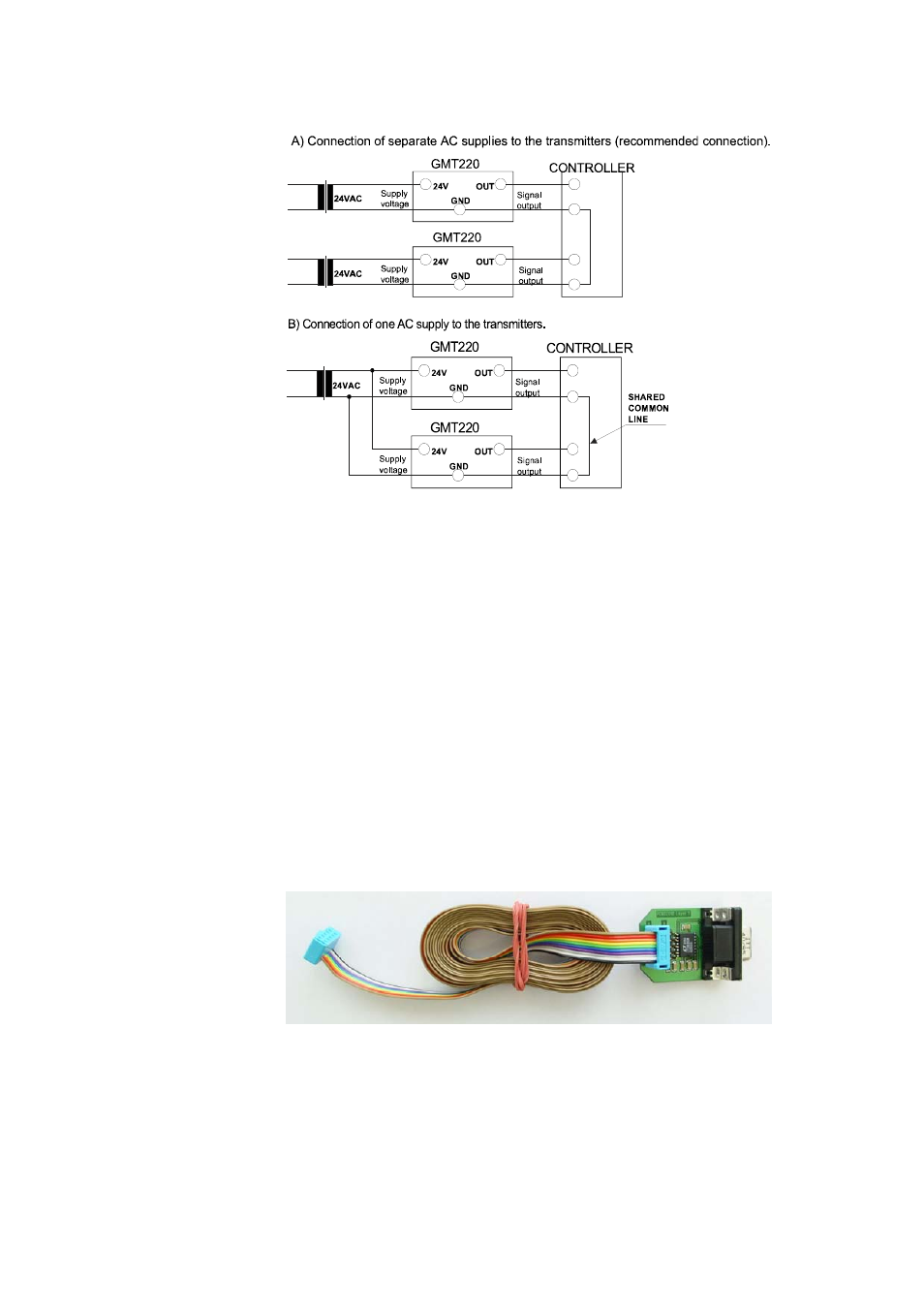
Figure 7
AC Connections
Relays
The relay output wiring is done at the left-hand side terminals on the
motherboard, see Figure 6 on page 15. When the relay trigger point is
exceeded, the relay switches ON. This function can be inversed by
disconnecting the corresponding relay jumper (L1 or L2).
The relay trigger points have been set at the factory as defined in the
order form. The points can also be changed with a PC and the optional
serial COM adapter 19040GM, see section Setting Relay Trigger Points
on page 21. The COM adapter 19040GM, see Figure 8 below, can be
ordered from Vaisala. For order information, see section Accessories on
page 37.
0808-001
Figure 8
19040GM Serial COM Adapter