Vfd – blower speed and frequency readings – State SBL85 390NE A User Manual
Page 34
32
Servicing should only be performed by a Qualified Service Technician
Two conditions must be met for the variable frequency drive to switch the blower from low speed to high
speed:
1. 100 - 120VAC must be supplied to the VFD input.
2. The ignition control closes a contact through the high speed I/O module – VFD terminals LI2 and
+24V.
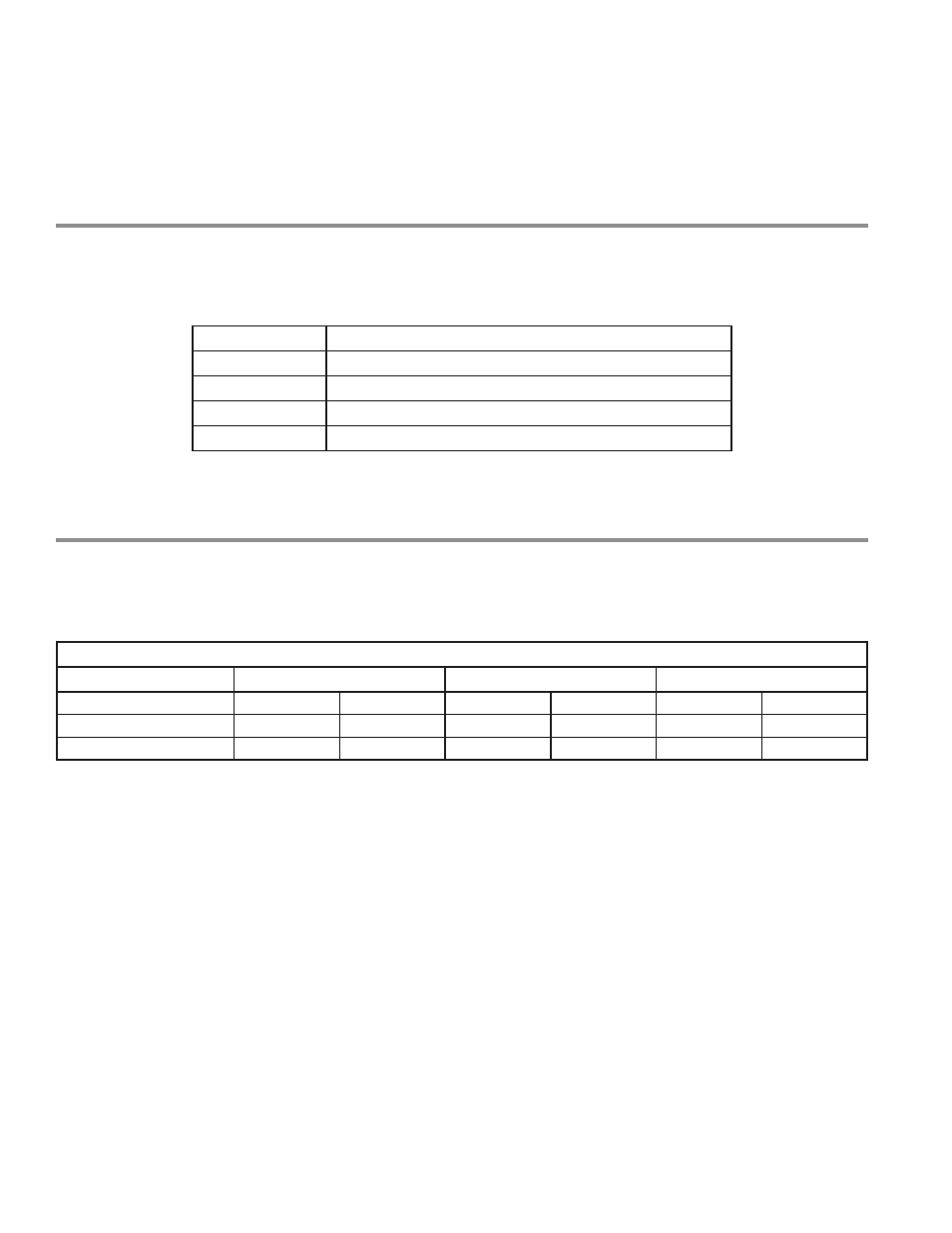
CHARACTERISTICS AND FUNCTIONS OF THE CONTROL TERMINALS
Display:
• 4 - digit display
• Display of numeric values and codes
TERMINALS
FUNCTIONS
COM
Common of analog and logic I/Os
LI1
Logic input for low speed
LI2
Logic input for high speed
+24V
+ 24 VDC supply provided by the drive
Line supply is at the top of the drive, the motor power supply is at the bottom of the drive.
VFD – BLOWER SPEED AND FREQUENCY READINGS
The logic inputs for the VFD are sent from the thermostat and ignition control through the low and high
speed I/O modules in the form of a contact closure. The chart below lists the nominal speed of the blower
and the frequency signal displayed by the VFD for low and high speed blower operation. If the water heater
exhibits poor run characteristics check the frequency display.
Nominal RPM – Frequency – VFD
Model
SBL95 199NE
SBL85 275NE(A)
SBL85 390NE(A)
Nominal RPM
Frequency
Nominal RPM
Frequency
Nominal RPM
Frequency
Low Speed
1550
53 Hz
1475
50 Hz
1475
50 Hz
High speed
4050
138 Hz
2550
101 Hz
4250
144 Hz