High limit switch/ digital thermostat – State SBL85 390NE A User Manual
Page 25
23
Servicing should only be performed by a Qualified Service Technician
BLOWER PROVER SWITCH
The blower prover switch is provided on the heater to verify that the fan is operating. It is a positive pressure
switch whose electrical contacts are
normally open. The blower prover switch electrical contacts will close
on a rise in pressure as the blower increases the pressure in the burner. This switch is connected to the
blower outlet pressure tap by a piece of silicone tubing. This tubing must be connected in order for the switch
to close the electrical contacts.
BLOCKED OUTLET SWITCH
The blocked outlet switch electrical contacts are
normally closed. The blocked outlet switch electrical
contacts will
open on a rise in pressure.
BLOCKED INLET SWITCH
The blocked inlet switch electrical contacts are
normally closed. The blocked inlet switch electrical contacts
will open when an
increase in negative pressure (vacuum) occurs in the intake vent pipe. The switch
is connected to the pressure tap on the PVC pipe connected to the inlet of the blower. When this switch
prevents the unit from igniting, most likely the intake is blocked by some means. Verify that the air intake pipe
is free of obstructions that may prevent air from entering the unit.
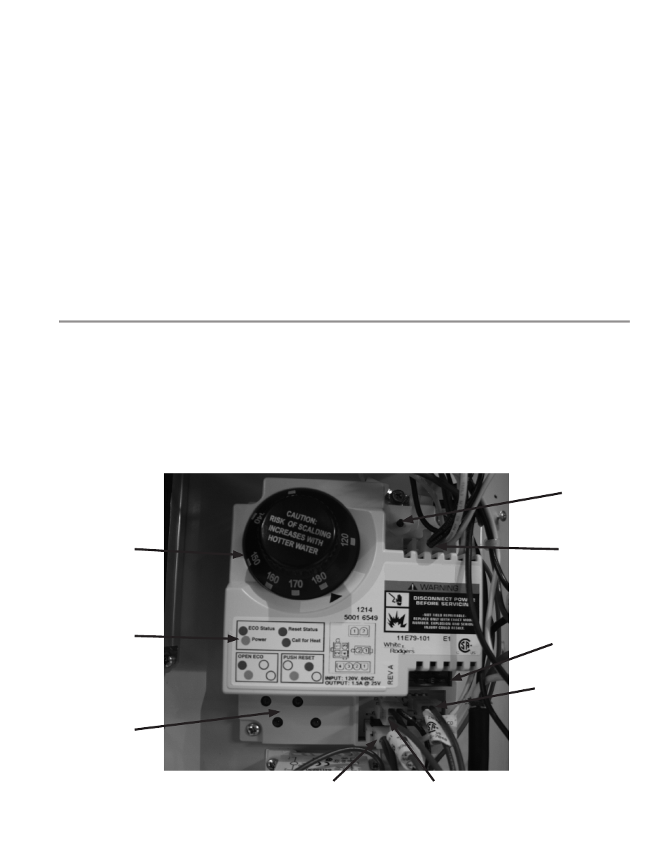
HIGH LIMIT SWITCH/ DIGITAL THERMOSTAT
The digital thermostat contains the high limit (energy cut out) switch. The high limit switch interrupts burner
gas flow should the water temperature reach 203°F (95°C).
In the event of high limit switch operation, the water heater cannot be restarted unless the water temperature
is reduced to approximately 120°F (49°C). The manual reset button on the front of the control then needs to
be depressed.
Continued manual resetting of high limit control, preceded by higher than usual water temperature is evidence
of high limit switch operation.
Contact your dealer or qualified service technician if continued high limit switch operation occurs.
Temperature
Adjustment
Dial
Display
LED Label
Display LED's
To Lower (E4)
Temperature
Probe
To Pressure Switches, I/O Modules & Ignition Control (E1)
Fuse
To 120V
supply
(E2)
Manual
Reset
To Upper (E3)Temperature Probe