Legend – State SBS100 76NE User Manual
Page 31
31
NOTES
:
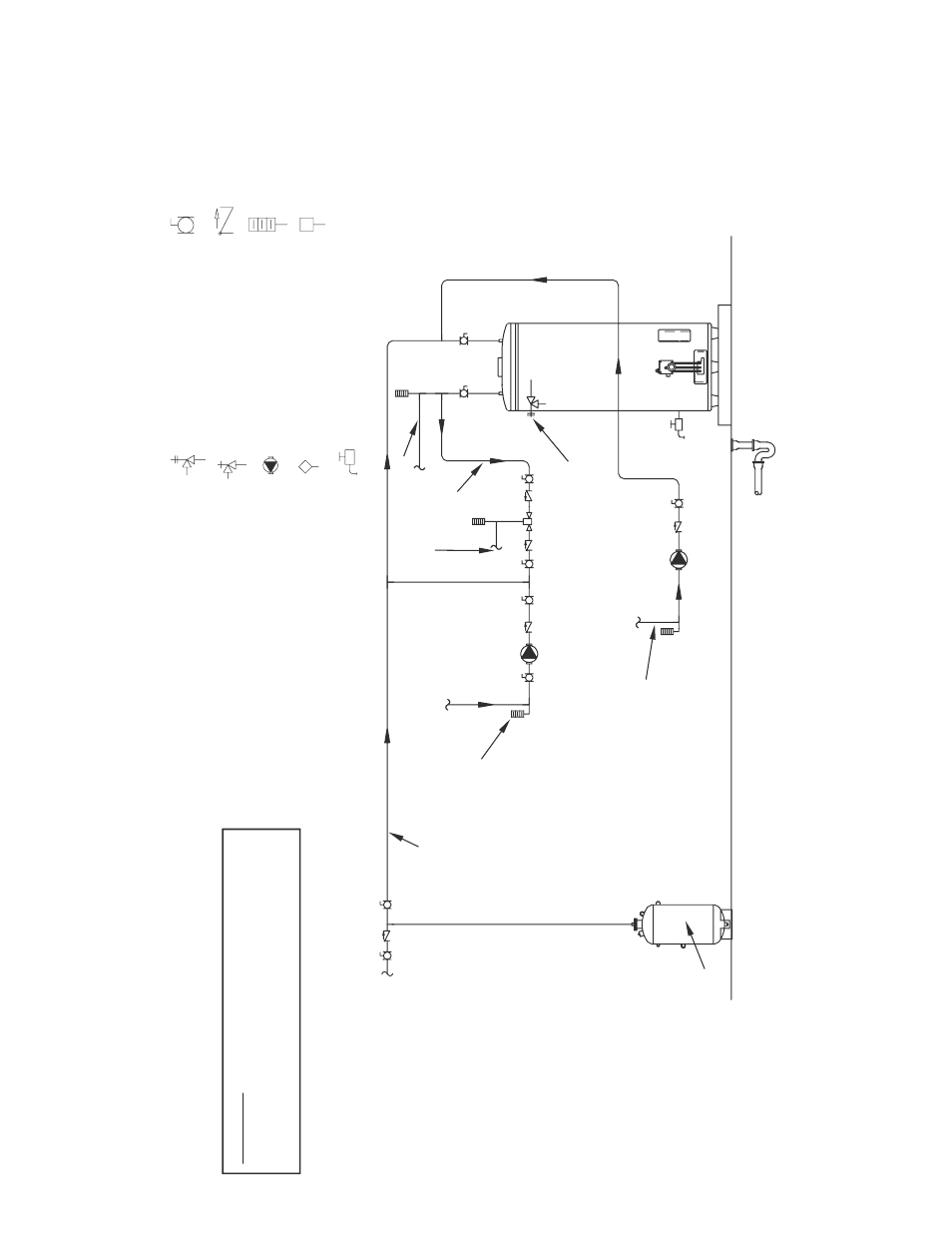
1.
Preferred piping
diagram
.
2.
The temperature and pressure relief valve setting shall not exceed pressure rating of any component in the system
.
3.
Service valves are shown for servicing unit. Howeve
r, local codes shall govern their usage
.
4.
The
T
ank
T
emperature Control should be wired to and control the pump between the water heater(s) and the storage tank(s)
.
5.
The water heate
r’s
operating thermostat should be set 5 degrees F higher than the
T
ank
T
emperature Control
.
SINGLE F
LUE
- (1 UNIT) WITH MIXING
VA
LVE
TWO
TEMPER
ATURE
LEGEND
TEMPER
ATURE & PRESSURE
RELIEF
VA
LVE
PRESSURE RELIEF
VA
LVE
CIRCUL
ATING PUMP
TA
NK
TEMPER
AT
URE CONTR
O
L
DRAIN
FUL
L PO
R
T BAL
L
VA
LVE
TEMPER
ATURE GAGE
W
ATER FLOW SWITCH
CHECK
VA
LVE
W
ARNING:
THIS DR
AWING SHOWS SUGGESTED
PIPING CONFIGUR
ATION
AND OTHER DEVICES;
CHECK WITH LOCA
L CODES
AND ORDINANCES
FOR
ADDITIONA
L REQUIREMENTS.
HOT WATER RETURN
MINIMUM 10
´´ to
1
2´
´
HOT WATER OUTLET
TEMPERED
WATER RETURN
TEMPERED
WATER OUTLET
COLD WATER SUPPLY
LINE
TEMPERATURE
CONTROL
COLD
HOT
EXPANSION
TANK
PIPE T&P TO OPEN DRAIN