State Standard Systems User Manual
Page 28
28
startup / sYstem settinGs
The AC power cord should be plugged in to an appropriate 115V outlet. The controller will enter an initialization phase in
which the operating control lamp will flash red and green. After the initialization period the controller will be in automatic
operation with the default settings active.
The pre-adjusted system scheme is ARR 1. Other system settings are available, but this setting should not be changed
for the system included in this package.
The controller is now ready for operation. The following system settings should be made as indicated. The operational
system channels are listed in order of appearance by pressing the forward (1) button.
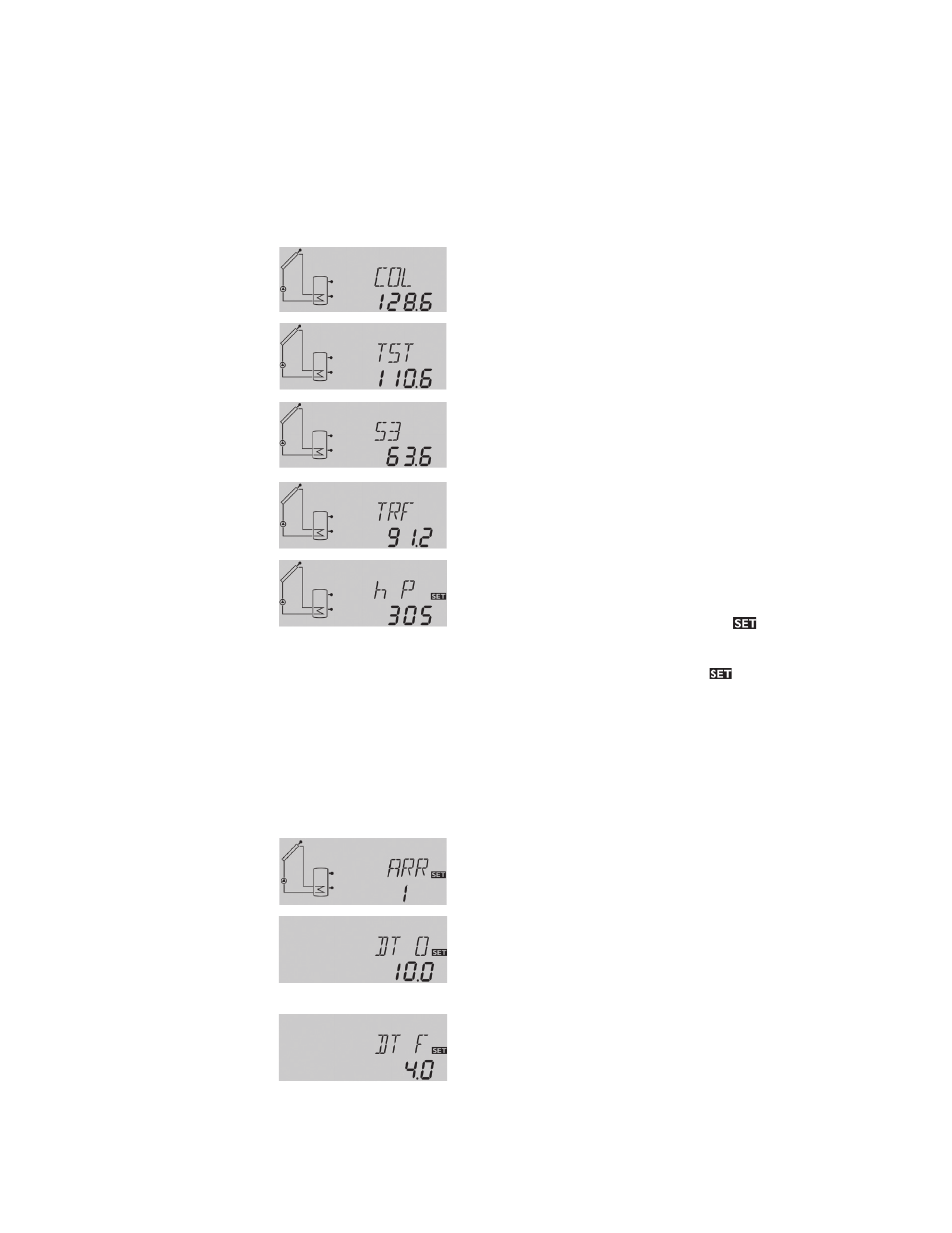
col:
Collector Temperature
Display range: -40 to +482 °F
Shows the current collector temperature.
tst:
Tank temperature
Display range: -40 to +482 °F
Shows the current tank temperature (from tank bottom sensor).
s3, s4:
Additional sensor temperature
Display range -40 to +482 °F
Shows the current temperature of the corresponding optional
sensor (without control function).
S3 and S4 are only indicated if the temperature sensors are
connected.
trf:
Temperature return flow
Display range -40 to +482 °F
Shows the current temperature of the optional temperature
return flow sensor (S4) when the heat quantity measurement
option is activated.
hp:
Operating hours counter
Display channel
The operating hours counter adds up the solar operating hours
of the pump. Full hours are shown on the display.
The total operating hours can be reset. When the operating
hours channel is selected the symbol
is permanently
shown in the display. The set button (3) must be pressed for
approximately 2 seconds in order to go into the reset mode
for the counter. The display symbol
will be flashing and
the operating hours will be set to 0. In order to finish the reset
procedure the set button (3) must be pressed in order to
confirm.
In order to interrupt the reset procedure no button should be
pressed for about 5 seconds. The controller will automatically
return to the indication mode with the previous total.
Once the final display channel is reached the remaining system setting channels may only be accessed by holding the forward (2)
button down for approximately 2 seconds. The following setting channels will then be shown:
arr:
System arrangement setting
Shows the current system configuration setting. Arrangement
1 should be used for the system in this package and this setting
should not be changed.
dto:
Switch-on temperature diff.
Adjustment range
2.0 to 40.0 °F
recommended setting: 10.0
Primarily the controller works in the same way as a standard
differential controller. If the switch-on difference, DT O (collector
temperature sensor reading minus the tank sensor reading), is
reached the pump is activated.
dtf:
Switch-off temperature diff.
Adjustment range
1.0 to 38.0 °F
recommended setting: 4.0
If the switch-off temperature, DT F, is reached the pump is de-
activated.
Note: the switch-off temperature must be at least 2 degrees
lower than the switch-on temperature.