A.R.I. D-070 EN User Manual
Maintenance instructions
MAINTENANCE INSTRUCTIONS
COMBINATION AIR VALVE
MODEL D-070
GENERAL
1. The periodic maintenance of the air valve is an integral part in the proper
regimen of water pipeline maintenance.
2. The air valve should be maintained at least once a year in accordance with the
quality of the water and the types of fluid composition in the system.
INSTALLATION
Before installing the Model D-070 air valve, make sure to flush and drain the
pipeline of all dirt and solids that may be in the line.
Caution in the choice of tools: Tools used for installation need to be compatible
with the valve parts, especially the bolts, in order to protect the valve parts and
coatings from damage.
Installation of an isolating valve: Imperative that an isolating valve be installed
under each air valve to enable the performance of periodic maintenance.
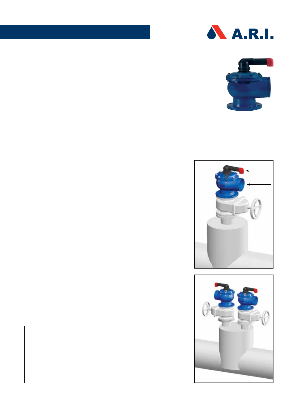
Installation of a riser: It is recommended to install the Model D-070 air valve
on top of a riser (see fig.1). Diameter of the riser should be at least one-half the
diameter of the pipeline.
Manifold: When the valve is installed on a manifold, the air valves should be
installed only on a welded manifold. They should be installed in a manner that the
drainage port openings should face in opposite directions (see fig. 2).
DRAIN PORT
1. Drainage angle: It is recommended installing a drainage angle at the drain
port (#1) exit; the diameter of the drainage angle should be at least the
diameter of the drain port.
2. Maintain an open drain port: Do not seal or block the opening of the valve
drain port (#1).
3. Warning on emission of water: The normal operation of the valve includes
water emissions under pressure. Ensure that the drain port (#1) is not
directed toward electrical elements (pumps) or people.
4. Caution: Do not put hands or objects into the drainage port (#1).
5. Drainage Pipe: Drainage pipes can be connected to the drainage angle
to direct the emission water. The end of the drainage pipe should remain
completely open and unobstructed. Do not connect a drainage pipe to the
upper drainage port (#2).
WARNING
Perform the following operations prior to maintenance or removal of the air
valve from the pipeline:
1. Shut the isolating valve (fig.2) on the riser below the air valve.
2. Slowly open cover bolts (D,6) alternately until water and air start to be
released. Wait until all the water and air cease to be released before continuing
3. Continue to open the bolts slowly, making sure that the pressure has been
released from inside the air valve prior to maintenance/removal from the
pipeline.
Drain Port #2
Drain Port #1
Fig. 1
Fig. 2 Manifold