Pop & Lock PL8660 User Manual
Pop & Lock For the car
Installation Instructions
Tailgate Lock
PL8660 series
Honda Ridgeline
2005 and Up
With or Without
Backup Camera
Package Contents: Lock Bezel, 2 keys, Mounting Bracket,
Locking Bolt Linkage, Crank Linkage,
2 Screws #8-32 x 1 1/2", 1 Bolt 1/4" x 2”
Locking Bolt Linkage and Slide Bolt
Long and Short Wire Harness, Zip Ties
Tools Required: 10 MM Socket, T40 Torx Bit, Phillip Head
5/32” Allen Wrench
Rubber Mallet
Power Drill
3/16” (or 5MM), 1/2" (or 12MM) Drill Bits
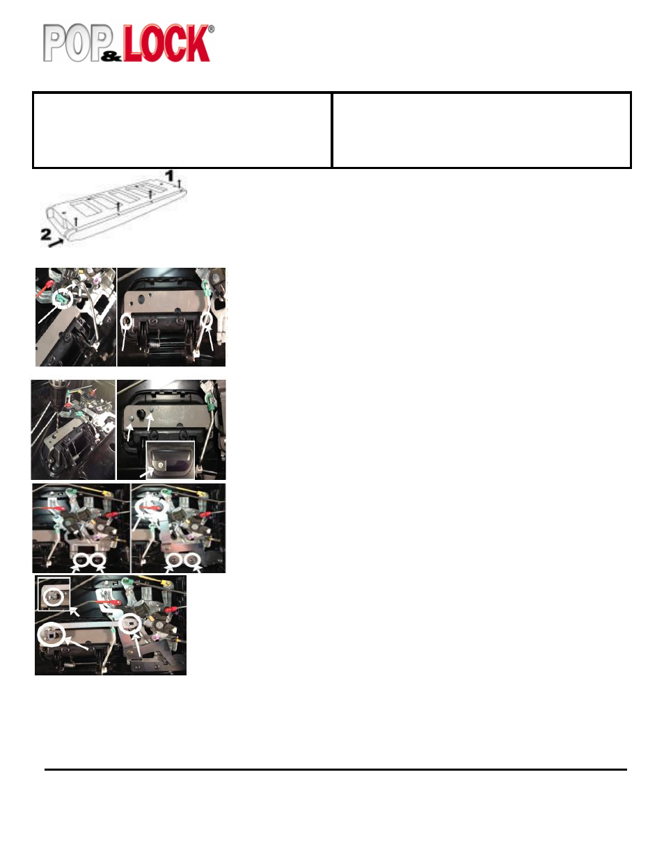
STEP 1 - Lower the tailgate. Remove the four Phillips head screws from the top trim, slide the
trim to the right (passenger) side using a rubber mallet and lift to remove it. Apply downward
pressure on the top trim if it bows up. Remove the white clips that remain on the tailgate by
turning them 45 degrees to pull out. NOTE THE ORIENTATION BEFORE REMOVEL.
Remove the T40 torx screws holding the interior trim panel and lift it off.
STEP 2 - Remove the handle rod from mechanicals by turning the green rod clip and
pulling the rod out of the clip. Swing the rod up and out of the way. Remove the two
screws holding the factory handle in place; there are tabs that will hold the handle
from falling out of the tailgate, but for extra assurance hold the handle in place so not
let the handle to fall. Install the mounting bracket over the back side of the handle and
reinstall the two screws and tighten. You may need to file the washer down go get the
bolt to fit. Reinstall the handle rod. The handle should now look like picture.
STEP 3 – Using the bracket holes as a template drill the two 3/16” (or 5MM) holes
and one 1/2" (or 12MM) hole. Insert the lock assembly from the front of the bezel
inserting the shaft through the 1/2" hole and aligning the two mounting holes on the
bezel with the mounting bracket. Insert the 2 supplied 8-32 x 1 1/2" screws
through the mounting bracket in the bezel. Tighten the screws. DO NOT OVER
TIGHTEN. IF LOCK ASSEMBLY BINDS LOOSEN SCREWS UNTIL THE
KEY MOVES FREELY!
STEP 4 – Remove the two mechanical assemble screws. Mount the POP N LOCK
bolt linkage under the upper latch rod as shown using the existing two mechanical
assemble screws. The lock assembly should look like picture.
STEP 6 – Check the functioning of the lock.
Technical Support:
Call 1-800-342-5911
STEP 5 – Install the crank rod assembly by holing the slotted end onto the bolt linkage and the
square hole to the end of the lock assembly shaft. Insert the 1/4" x 20 x 2” screw into the shaft and
tighten.
Lock – Turn the key to the right (passenger side) to the
two o’clock position and then back to 12 o’clock to lock.
Unlock – Turning the key to the left (driver side) to the
ten o’clock position and then back to 12 o’clock to
unlock.
For instructions in color please visit
our website at popandlock.net