Generator, Transfer, E 18 – Outback Power Systems GS8048 Operator Manual User Manual
Page 20: 18 a, E 18.), Operation
Operation
18
Input Mode and Limits). The settings are titled Voltage Limit Lower and Upper. When this setting is
adjusted, it applies equally to L1 and L2.
There can be side effects to changing the range of allowed voltages. See page 18.
Each of the AC inputs has a settable connection delay. This is intended as a warmup period which allows
an input source to stabilize before connection.
∼ The default setting for the Grid input is 0.2 minutes (12 seconds).
∼ The default setting for the Gen input is 0.5 minutes (30 seconds).
These items are adjustable in the appropriate menu of the MATE3 (Grid AC Input Mode and Limits or Gen
AC Input Mode and Limits).
NOTES:
Certain input modes
s
uch as
Mini Grid may prevent the inverter from accepting AC power even if electrical
conditions are met. (See page 13.)
Several items external to the inverter may prevent the inverter from accepting AC power even if electrical
conditions are met. One is the High Battery Transfer mode, which is operated by the MATE3 system display.
(See page 33 and the MATE3 Owner’s Manual.) Another is the MATE3’s
AC INPUT hot key menu, which can
order all inverters to disconnect when set to
Drop. (See the MATE3 manual.)
The inverter has additional criteria that control whether it sells power. The inverter may accept AC power but
refuse to sell if the acceptance criteria are met, but the grid-interactive criteria are not. (See the
Grid Tied
input mode on page 11.)
Generator
A generator should be sized to provide enough power for all inverters, both for loads and for battery
charging.
It is usually recommended that the generator be sized at twice the wattage of the inverter system.
Many generators may not be able to maintain AC voltage or frequency for long periods of time if they
are loaded more than 80% of rated capacity.
The generator is required to have a stable output before its power is accepted by the inverter. Some
generators with less stable or uneven outputs may not be accepted. The use of the
Generator input
mode may assist with this problem.
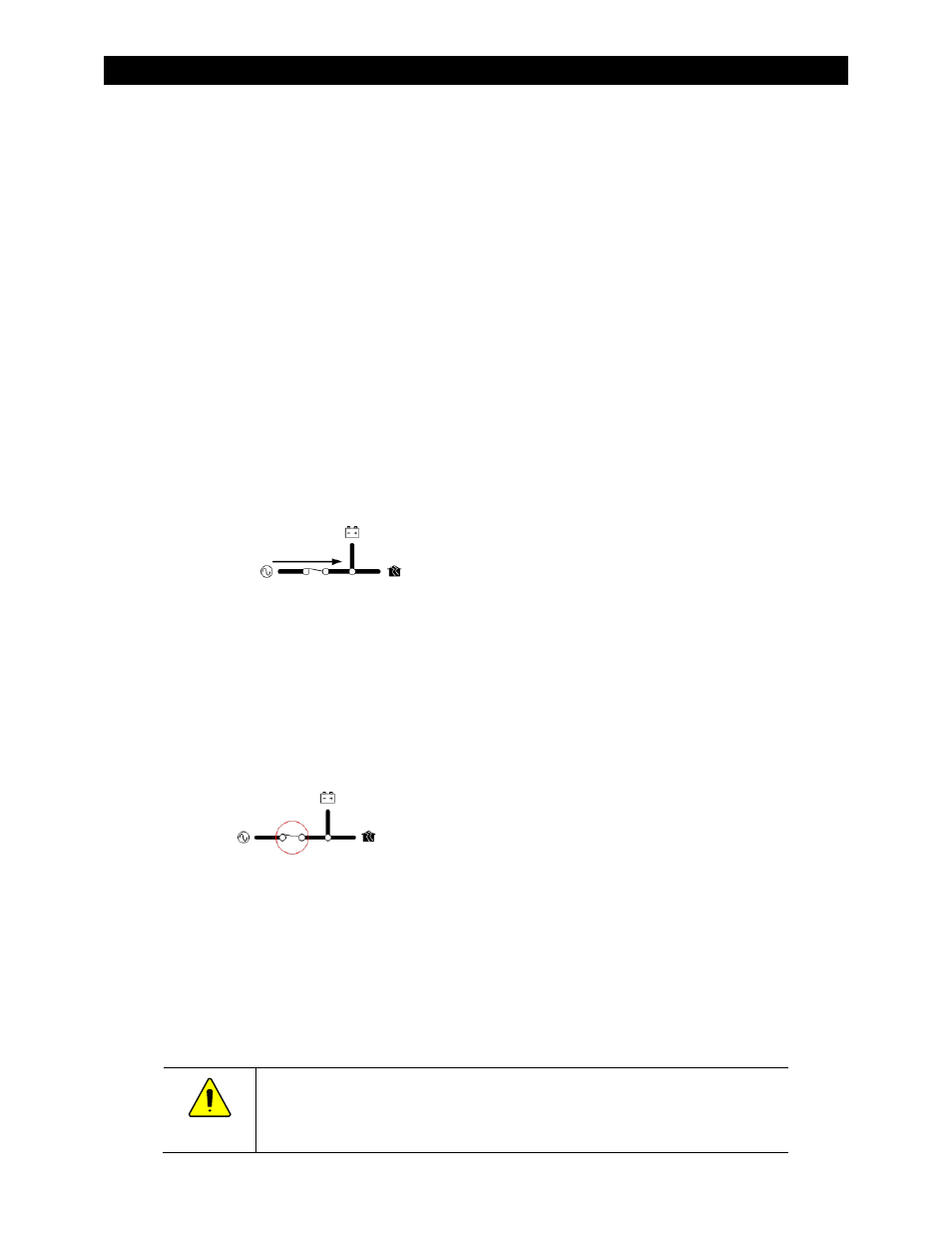
Transfer
The inverter uses a transfer relay to alternate between the states of inverting and of accepting an AC
source. Until the relay energizes, the L1 and L2 output terminals are electrically isolated from the
input that is in use. When it closes, the L1 input and output terminals become electrically common.
The same is true for the L2 input and output terminals. (The terminals for the unused input remain
isolated during this time.) When the relay changes states, the physical transfer delay is approximately
25 milliseconds.
The relay contacts are limited to 55 amps per phase or leg. The continuous loads on that output
should never exceed this number. When connected to an AC source, the Radian inverter cannot limit
the load current. An overload condition is possible.
CAUTION: Equipment Damage
Current draw in excess of the inverter’s transfer relay rating can damage the transfer
relay. This damage is not covered by warranty.