Actron CP8203 User Manual
Precautions, Installation, Troubleshooting
1
VACUUM / ECONOMETER / BOOST GAUGE INSTRUCTIONS
INDICADOR DE VACIO / DE ECONOMIA/DE REFUERZO INSTRUCCIONES TENSIÓN 12 V
VACUOMÈTRE / ÉCONOMÈTRE / MANOMÈTRE DE PRESSION DE TURBO INSTRUCTIONS
These types of gauges measure the vacuum
and/or pressure existing within the intake mani-
fold of the vehicle. Different ranges or markings
cover different needs and applications. A vacuum
or econometer gauge measures the vacuum cre-
ated as the engine draws air into its cylinders. A
boost gauge measures the same vacuum as well
as the pressure when an external turbocharger
or supercharger pushes air into the engine. An
engine that is not supercharged or turbocharged
will generally have a vacuum reading between 12
and 18 Hg (inches of mercury) at idle. Check the
manufacturers specifications for more exact read-
ings for your engine at idle speed and other RPM.
All of these gauges can aid you in monitoring en-
gine efficiency, achieving the best fuel economy
and noticing engine malfunctions immediately.
PRECAUTIONS
1. Be sure the source of vacuum you pick is a
direct source and not in the brake booster or
other accessory line, otherwise the reading may
be inaccurate or unsteady.
2. Be sure your tubing and fitting connections are
complete and sealed, for a vacuum leak will
cause rough engine operation at idle, and in-
accurate readings.
INSTALLATION
For Gauges with a Barbed Fitting:
1. Find a location on your intake manifold where
you can either unscrew a plug in the manifold
or find a vacuum hose you can cut to splice in
a barbed T-Fitting.
2. From the tubing kit, either screw in the barbed
manifold fitting or splice the barbed T-Fitting
into a suitable vacuum line. This is done by
cleanly cutting the tubing and then pressing
each cut end of the tubing tightly into the op-
posing barbs of the T-Fitting.
3. Unroll a few feet of vacuum tubing and press
the end tightly into the remaining barb of the
T-Fitting.
4. Route the remaining tubing through the fire wall
into the gauge, leaving at least one 3 or larger
loop in the tubing before it enters the fire wall
and protect the tubing from any rough edges
of the fire wall. Press the tubing tightly onto
the barb on the back of the gauge.
5. Start the engine and check for proper gauge
operation. Refer to the How To Use section
on the next page.
For Gauges with 1/8 NPT (threaded) Fitting:
1. Find a location on your intake manifold where
and ferrule over the end of the tubing as show
in Diagram 1.
4. Insert the tubing into the engine fitting and then
tighten the hex nut into the engine fitting.
5. Route the remaining tubing through the fire wall
to the gauge, leaving at least one 3 or larger
loop in the tubing before it enters the fire wall
and protecting the tubing from any rough edges
of the fire wall.
6. If the hex nut adapter is not attached to the
gauge, then wrap Teflon tape around the
adapters threads and attach the hex nut
adapter. Attach the tubbing as in Steps 3 and 4.
Refer to Diagram 2.
7. Complete the mounting of the gauge.
8. Start the engine and check for proper gauge
operation. Refer to the How To Use section
on the next page. For boost gauges, you will
need to consult manufacturers specifications
for the RPM and pressure values that provide
the maximum boost and for the RPM value
that transfers to boost from vacuum.
TROUBLESHOOTING
1. If your engine idles roughly, check the tubing
and fittings for leaks. Sealing tape or compound
can usually be used to solve these leaks.
2. If the gauge vacuum readings changes when
you can screw in the engine fitting directly or
using the adapter included with the gauge.
Manifolds often have removable plugs.
2. Screw in the adapter (if needed) and engine
fitting into the manifold at the location you se-
lected.
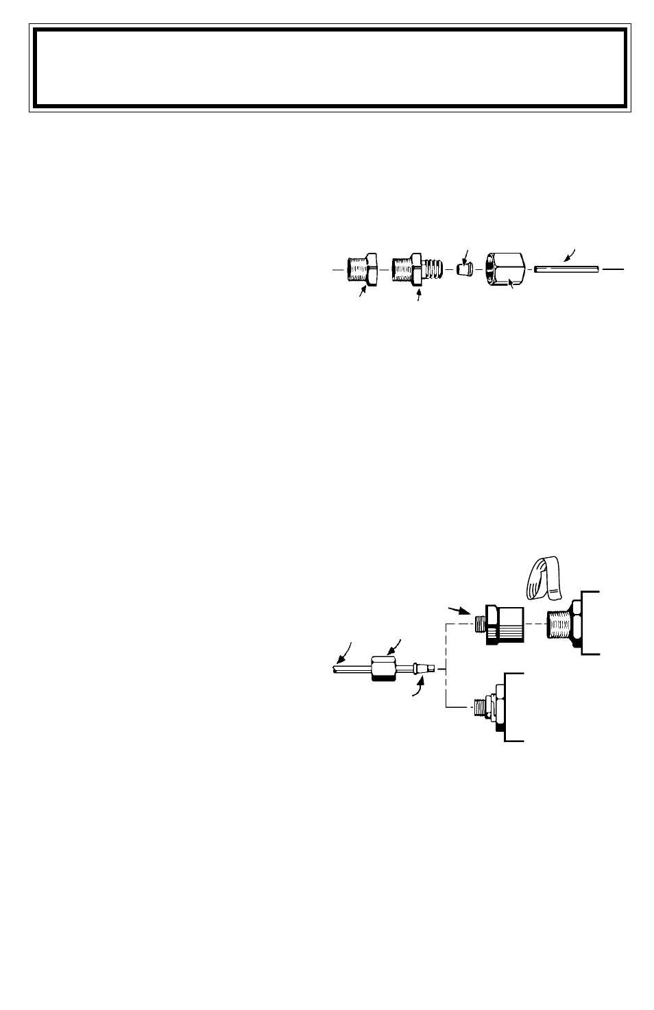
3. Uncoil a few feet of tubing and slide a hex nut
Diagram 1
FERRULE
TUBING
ADAPTER
ENGINE
FITTING
HEX NUT
PARA NOMBRE, DOMICILIO Y TELEFONO DE IMPORTADOR: VER EMPAQUE.
Diagram 2
HEX NUT ADAPTER
HEX NUT
TUBING
FERRULE
1/8 NPT
GAUGE
COMPRESSION
FITTING GAUGE
TEFLON TAPE