Panels / display/ remote layout, Continued – Anthem AVM 20 v2 User Manual
Page 20
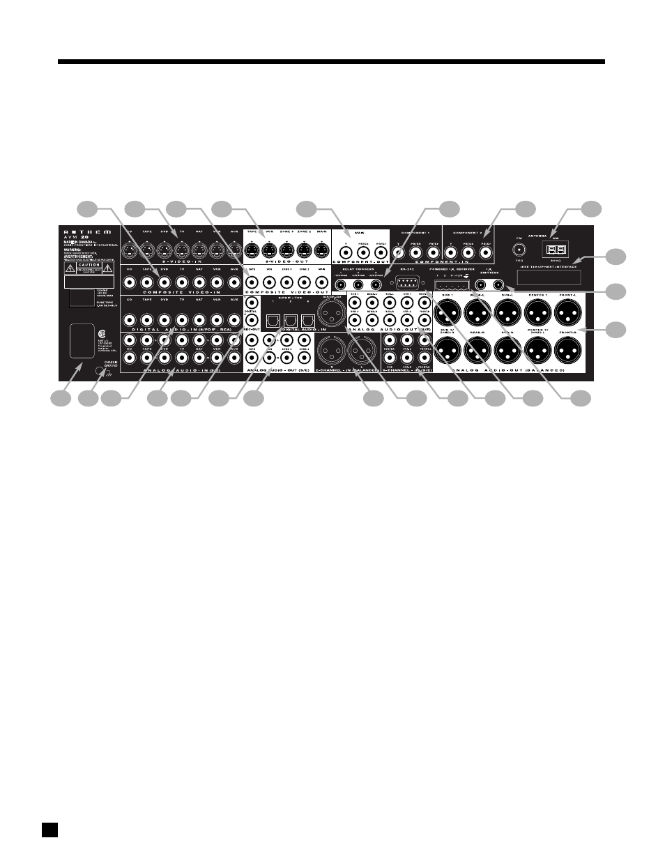
13
1
– 7 Composite Video RCA Inputs
2
– 7 S-Video Inputs
3
– 5 Composite Video RCA Outputs
4
– 5 S-Video Outputs
5
– Component Video Outputs (3 Jacks/ea)
6
– 3 Relay Trigger 3.5mm Outputs (Assignable)
7
– 2 Assignable Component Video Inputs (3 Jacks/ea)
8
– FM and AM Antenna Inputs
9
– IEEE 1394/PHAST Interface provision*
10 – 2 I.R. Emitters
11 – MAIN Analog Audio Balanced XLR Output (10 Jacks)
12 – 3 12V powered Infra Red (IR) 3.5mm Inputs
13 – RS-232 Interface Port (Bi-Directional)
14 – MAIN Analog Audio RCA Output (10 Jacks)
15 – Analog Audio 6-Channel RCA Input (6 Jacks)
16 – Digital Audio AES / EBU Input (Assignable)
17 – Analog Audio 2-Channel XLR Input (2 Jacks)
18 – ZONE2, ZONE3, and REC Analog Audio RCA Outputs
19 – 3 Digital Audio Toslink Inputs (Assignable)
20 – 2 Digital Audio RCA REC Outputs
21 – 7 Analog Audio RCA Inputs (L/R Jacks)
22 – 7 Digital Audio RCA Inputs
23 – Ground Terminal
24 – Power Cord Connection
3.3
REAR PANEL LAYOUT
The rear panel of the AVM 20 contains all connections, such as power connection, audio and video inputs and outputs, antenna
connections, and the RS-232 port which allows software upgrades and external control of the AVM 20.
* Interface card requires installation by a qualified dealer.
See section 4 for complete information on Rear Panel connections.
3. PANELS / DISPLAY/ REMOTE LAYOUT
continued …
22
23
24
21
19
18
20
13
14
15
12
16
17
7
6
8
9
10
2
4
5
1
3
11