Pypes Performance Exhaust SGF70 User Manual
Sgf70
SGF70
409 Stainless Steel header/cross-member back exhaust system for
1967-81 GM F-bodies
SGF70: 2-1/2” w/ x-pipe, cross-flow muffler and qtr exit tailpipes
1. Begin by placing the vehicle on a lift or four jack stands at maximum height
to aid in an easier installation. To help ease the installation, pre-fit all the components
into a complete system on your garage floor, using the diagram provided.
2. First, remove the existing exhaust system from the headers or exhaust manifolds
back. You can also remove any hanger mounted to the frame as your new kit includes factory
reproduction hangers.
3. Now it’s time to install your new components. Begin by test installing your new
tailpipes. The new repro tailpipe hanger will get mounted in the factory location on the outside
of the frame rail just in front of the leaf spring shackles. Slide the spoon hanger welded to the
tailpipe into the hanger just installed. 67-69 owners may want to remove the spoon hanger and
utilize the factory qtr exit tailpipe hanger. Here is where the muffler installation will begin. The
Crossflow muffler should sit square and parallel, between the gas tank and the rear. The driver
side tailpipe will go in the bottom inlet of the muffler and the passenger side into the top inlet
opposite side. Next, the over the axle portion (mid-pipes) of the tailpipe can be installed. Driver
side will go in the top of the muffler and the passenger side into the bottom of the opposite side.
Final adjustments will be done when the entire system is installed. The muffler hangers will
get mounted to the rear seat pans just in front of the rear. On some models, you maybe able
to utilize the original muffler and tailpipe hangers. If you so choose, custom hangers may be
fabricated, let your creativity shine…
4. Next, its time to install the x-pipe. This is where trimming of the tubing may be
required for the optimum fit. Install the rear “X” member into the mufflers first. You are aiming
to have the center “X” land approx 8-12 inches behind the tail shaft of your transmission and
centered under the driveshaft. Also, the center plate on the “X” has an arrow stamp which must
point forward. Trim the rear legs as needed to put your “X” in the proper location. Quick tip: If
the rear suspension is unloaded, you can push the center “X” up until it just about touches the
drive shaft as it will never hit once t he suspension is loaded. Slide the front legs into the x-pipe.
They should end somewhere close to the humps in your transmission cross-member. On some
applications, the front “X” legs may not be centered in the humps but line up to your headers or
down-pipes. This is fine as the system will not hang too low. Be extra careful when measuring
and cutting. A helpful tip: Line up the front legs under the center “X” to mark your cut lines mak-
ing sure to line them up with you headers or down pipes. Note: Convertible owners will require
the body brace spacer to be lowered using our RPE631FA body brace spacer kit.
5. Connect the front legs of the x-pipe to the headers (collector reducers) utilizing the
two 1ft collector extension pipes. Trimming the length may be required. Do not connect the
x-pipe directly your headers. If down pipes (see down-pipe instructions) are used, make sure
they end close to the rear side of the transmission cross member. If they are too long they must
be trimmed. Some header applications require custom collectors due to the header not ending
square and parallel to the car. For proper system fit, you collectors must run parallel with your
rocker panels.
6. Install Optional EVT49 Quarter-Exit tips or EVT58/59 Rear-Exit tips. Installation of
1976-81 TA tips will require extra material for proper tip position.
7. Finish the system by making all your final adjustments to position the x-pipe, mufflers
and tailpipes. Now tighten all the clamps (Warning: tightened clamps will leave marks in the
tubing, making removal or adjustments extremely difficult) or for the best fit weld all the slip
joints. The 409 stainless can be welded with your standard mig welder, and is highly recom-
mended when possible.
Now it’s time to fire up that muscle car and enjoy your
new Pypes Performance Exhaust.
Pypes Performance Exhaust
2705 Clemens Road Bldg 105A Hatfield, PA 19440
800-421-3890 (voice) 267-638-3507 (fax)
www.pypesexhaust.com
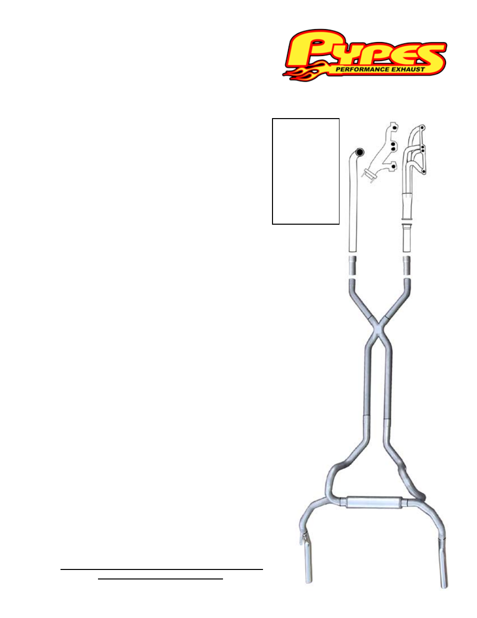
(A) Manifold (optional)
(B) Header (optional)
(C) Downpipe
(optional)
(D) Collector Reducer
(optional)
(E) Collector
Extensions
(F) X-pipe Assembly
(G) Mid-pipes
(H) Crossflow Muffler
(I) Tailpipes
(J) Tips (optional)
(A)
(B)
(C)
(D)
(E)
(F)
(G)
(H)
(I)
(I)
(J)
(J)
Thanks again for purchasing your new 409 stainless steel Pypes Perfor-
mance Exhaust header/cross-member back system. Please be sure to
confirm all the components in the kit were received in your shipment before
beginning installation. These kits will include (1) X-pipe kit, (1) Race Pro
designed Crossflow Muffler, (2) tailpipes, (2) mid-pipes, (2) collector exten-
sions, (2) muffler hangers, (2) tailpipe hangers, (12) clamps, and (1) bonus
pack. If you find any component missing, please contact our office at 800-
421-3890 for replacement. Installation of this kit will require some simple
hand tools; box wrenches, deep sockets w/ ratchet, extension, a saws-all
and some penetrating lubricant. For a quicker and tighter installation, air
tools are recommended. Fully welding the system is always recommended
when possible. Technical assistance is available both online at www.pype-
sexhaust.com or 800-421-3890. Also, our online Installation Gallery is a
great assistant during your installation,
visit www.pypesexhaust.com/pictures.html