Removing and drilling the intake manifold – Nitrous Express DIRECT PORT (NOZZLE SYSTEM) User Manual
Page 2
REMOVING AND DRILLING THE INTAKE MANIFOLD
Before any modifications are made to the engine compartment, we suggest that you make a diagram of all hoses, wiring, and linkages.
1. Remove the intake manifold. If you have question regarding this step please consult a service manual on your engine type.
2. Mark the center of each runner approximately 1 -1.5 inches from the manifold flange. This distance is not critical, however the higher
up the runner the nozzle is placed the harder the “Hit” when the system is engaged.
3. This step is critical to a successful installation.
The use of a Bridgeport s t yl e mill is suggested. The nozzle mounting hole should be “tilted” back toward the manifold
plenum 1-1.5 degrees to ensure adequate valve cover clearance. Each hole must be in alignment, front to rear, and top to bottom.
If your system is furnished with Shark Nozzles drill each runner using an “R” bit. Tap each hole to a uniform depth using a
1/8
NPT tap. If your system is furnished with Piranha or SSV nozzles drill each runner using a 1/4” bit. Tap each hole to a uniform depth
using a 1/16 NPT tap.
4. Debur the holes inside and out.
5. Install t h e nozzles in the tapped holes using a Teflon based paste sealer. Be sure each nozzle is installed to a uniform depth.
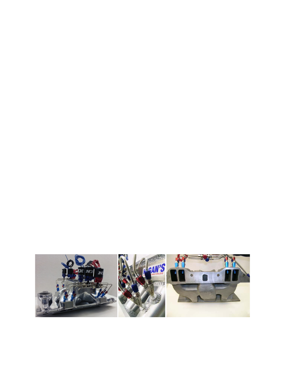
6. Using the pictures in Illustration “B” as a guide, map out how you want your NX system to look after it is installed.
7. If using standard distribution blocks skip to step 8. If you have purchased an NX Next Generation
Rail s ys t e m, position the rails on the
manifold above the previously installed nozzles and mark the location of each fitting on a rail “Flat”. Note: The rail may b e shortened,
by cutting an equal length off of each end at this time if it is excessively long. Drill the rail using an “I” bit. Using a bottom hole tap,
thread these holes 5/16 x 24. Install the rail fittings using NX red liquid thread sealer. Using a, snug fitting, aircraft style, drill bit, debur
the entire length of the inside diameter of each rail orifice. Drill both ends of each rail to a
1” depth with an “R” bit and tap 1/8 NPT.
Debur the entire rail again thoroughly; a n y debris left inside the rails will cause future trouble. Install the fuel and nitrous solenoids
on the end of the appropriate rail, again using NX thread sealant. Install the furnished 1/8 NPT plugs on the unused rail end. Note: The
fuel solenoids always mount in the front; the nitrous solenoids may be mounted on either end.
8. After d e t e r m i n i n g the desired p o s i t i o n o f each rail or distribution block, cut and debur the 3/16 stainless hard lines to the proper
lengths. Using a 37-degree flaring tool prepare one end of each line and install the appropriate color sleeve and B-nut. Starting on
both ends of each rail bend the stainless 3/16 tubing to position the rail as desired. Install a B-nut and sleeve, f l a i r and install t h ese
two “positioning” lines. Cut, bend, and flair each of the remaining lines to match the originals.
9. If you have purchased a conventional style NX system install the solenoids on the distribution blocks, using blue for nitrous and red for
fuel.
When using 3/16 inch compression fittings in distribution blocks, do not insert the tubing more than ½ inch into the compression fitting.
Inserting tubing too far into the compression fitting could block flow into the tubing.
Position the solenoids on each side of the manifold so
as not to interfere with any linkages or other equipment. Cut, bend, install B-nuts, sleeves and flair each 3/16 line to support the
solenoids in the desired location.
10. Using the supplied jumper lines and billet distribution “Y’s” connect the nitrous solenoids together and repeat the step on the fuel
solenoids.
11. After all installation on the manifold is complete flush all lines and orifices using compressed air. Attention to detail here will save you
time and money in the long run. Do not shortcut this step! Reinstall the intake manifold and carburetor; hook up all vacuum lines, and
linkages using the diagram prepared before disassembly. Reconnect the fuel lines and tighten securely.
12. Now install the nitrous supply line leading from the bottle to the nitrous solenoid. NOTE: Tape over both ends of the nitrous
supply line before
beginning. Route lines carefully to prevent the possibility of restricting any nitrous flow. If routed under vehicle,
locate and drill a
3⁄4 inch diameter hole in a suitable area near the bottle valve for the main line. Starting at the bottle nipple (Do not
attach to the bottle nipple yet) route the line to the engine compartment. Following t h e factory f u e l lines is usually the best path.
Note: Keep maximum clearance between all moving parts, suspension components and hot engine components, securing the supply line
where possible (“Zip-Ties” wo r k best here). Be especially careful of the feed line being n ea r any “HOT” electrical leads, e v en a small
spark will result in a nitrous leak. If the line is too long, coil the excess near the bottle, if it is too short; try rerouting the line to gain
length. If this does not work contact the factory for a custom length supply line. After the nitrous supply line is in place remove the
tape from both ends. Install the n u t a n d n i p p l e o n th e b o t t l e a n d tighten firmly. Before you attach the nitrous supply line purge it
of any foreign matter that may have accidentally en t e red the line during installation. Do so by removing the tape used during
installation and blowing compressed air t h r o u g h t h e f e e d line. (Have an assistant hold the end of the hose aimed away from the car
and any people. Wearing a glove is recommended). Immediately a f t e r the purging operation, connect the main feed line to the N2O
solenoids and the nitrous bottle, tighten securely.
ILLUSTRATION B