Merit Medical VP-210 PD Catheter Implantation System User Manual
Page 6
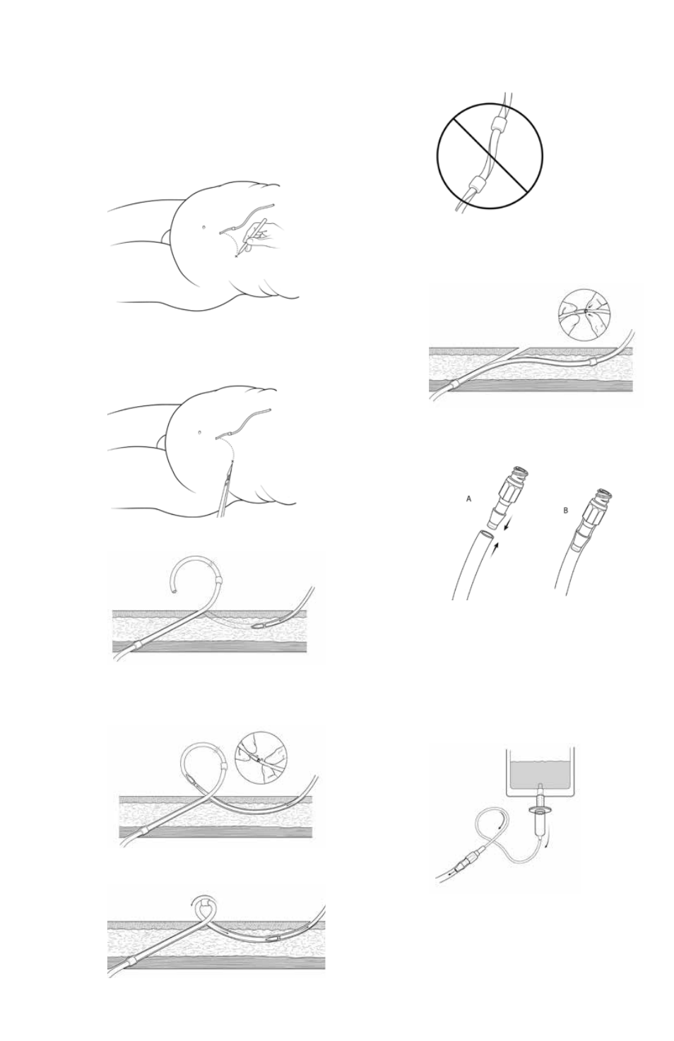
2. alternatively, if the Implantation Stencil was not
previously used to mark the exit-site:
lay the catheter on the patient’s abdomen to determine
the best exit-site location. That location should be lateral
to the primary site. Then, mark a spot so that the exit-site is
about 3-4 cm distal to the exit site cuff (Figure 33).
NOTE: For reduced infection and optimal placement, the
catheter should have a gentle, curved downward-facing
exit-site
Figure 33
3. anesthetize exit-site location and the tunnel path.
4. make a stab incision with #11 scalpel blade to full width
of blade at the exit site. (Figure 34).
Figure 34
5. Insert Tunnelor Tool at the exit-site (Figure 35).
Figure 35
6. advance Tunnelor Tool to primary insertion site.
7. Slide end of catheter over tip of Tunnelor Tool
approximately 3-4 cm. (Figure 36).
8. Secure catheter to Tunnelor Tool using sutures if desired.
Figure 36
9. Retract Tunnelor Tool and catheter into tunnel and out
of exit-site (Figure 37). WaRnInG: Do not dislodge the
distal cuff.
Figure 37
10. (optional) Create a space within the tunnel for the
distal cuff.
CAUTION: Check catheter at primary site and exit-site to
ensure the catheter is not twisted or kinked (Figure 38).
Figure 38
11. Push catheter off the Tunnelor Tool (Figure 39).
alternatively, cut the catheter off the Tunnelor Tool if
sutures were used.
Figure 39
12. attach catheter connector to catheter assuring
catheter is completely advanced to connector hub.
(Figure 40).
Figure 40
ChECkING CAThETER PATENCY
1. Deflate the abdomen if not already deflated from
steps above.
2. Test catheter patency by infusing 1 liter sterile saline
(Figure 41) after attaching appropriate transfer set to the
connector.
NOTE: It is helpful to place the patient in reverse Trende-
lenburg position. a steady outflow of fluid from the bag or
consistent drip confirms a well-functioning catheter.
Figure 41
3. attach cap to the connector or transfer set.