ADC AD-200 User Manual
Page 34
30
(a) To check and/or set the 1/8” (3.175 mm) GAP, use a Direct Spark Ignition (DSI) Gap
Feeler Gauge or similar device to determine GAP size. DO NOT USE FEELER TO
SET THE GAP, USE IT ONLY TO DETERMINE THE SIZE OF THE GAP. If
an adjustment is necessary, bend the ground rod to achieve the correct GAP, then recheck
the 1/8” (3.175 mm) GAP with a feeler gauge.
(b) The ALIGNMENT of the Ignitor/Flame-Probe Assembly in relation to the GAP on the
ignitor electrode and ground rod must be maintained in as vertical (straight line) a
position as possible (refer to the illustration below) otherwise the DSI module will
indicate a system malfunction and go into the “LOCKOUT” mode (the light emitting
diode [L.E.D.] indicator will BLINK “GREEN” CONTINUOUSLY).
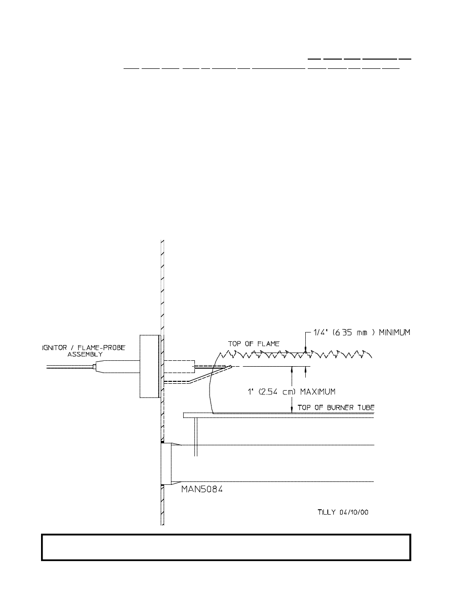
(c) The POSITIONING of the Ignitor/Flame-Probe Assembly is extremely important because
it provides the necessary feedback information to the DSI module. The flame-probe
electrode must be POSITIONED 1/4” (6.35 mm) minimum into the flame path (refer
to the illustration below) and must be POSITIONED 1-inch (2.54 cm) maximum
from the burner tube (refer to the illustration below) otherwise the DSI module will
indicate a system malfunction and go into the “LOCKOUT” mode (the L.E.D. indicator
will BLINK “GREEN” CONTINUOUSLY).
NOTE: To reset the DSI module if it is in the “LOCKOUT” mode, “Burner Control Fault” will display.
To clear this fault press the “CLEAR/STOP” key.