American Fibertek Net I/O N-664 User Manual
Page 10
10
Connecting contacts
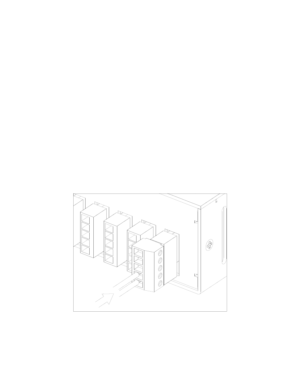
The N-664 has six ports for contact inputs (alarms) and contact outputs (aux). Each port
is a five pin header with a supplied plug with screw terminals. Customer connections to
the contact ports are made by securing stripped wire ends into the screw terminals.
Note: All connections to the screw terminals should be made with the terminal plug
removed from the unit, and with power disconnected from any customer equipment
being connected to the terminals.
Connecting an alarm input
Each contact block has two terminals which are used as an alarm/contact input. Viewing
the rear of the N-664, these two terminals are the lower two of each 5 pin terminal block.
These terminals are intended to be connected to customer equipment which will make or
break a connection between the two terminals, such as a door open switch or motion
detector contact output. It can be designated through the configuration web page if an
alarm condition will correspond to the connection being made or the connection being
broken.
To connect an alarm source such as a door switch or motion detector to the N-664, use
two wires, 16-28 AWG in size. Strip about ¼” of the insulation from the end of the wires
before inserting them into the terminal blocks. Tighten the terminal screws to secure the
wires in the terminal block.
Alarm Input Connection
Note: the electrical connection to the alarm inputs are to be connected only to isolated
contact closure devices, and must not be directly connected to any external power or
ground source. Directly connecting either terminal of the alarm input to any voltage
source or external ground may damage the N-664.