Disassembly procedure flowchart, Chapter 3 63 – Acer 420 User Manual
Page 71
Chapter 3
63
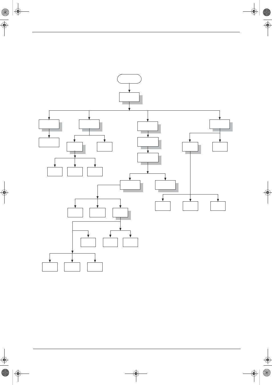
Disassembly Procedure Flowchart
The flowchart on the succeeding page gives you a graphic representation on the entire disassembly sequence
and instructs you on the components that need to be removed during servicing. For example, if you want to
remove the system board, you must first remove the keyboard, then disassemble the inside assembly frame in
that order.
Start
Battery
RAM Door
HDD Module
Hinge Caps
ODD module
Memory
Ax2
Bx2
ODD
Holder
ODD
Assembly
Fx4
Ex2
ODD Door
ODD PCB
Board
ODD
Drive
HDD
Cover
HDD
Assembly
Hx4
HDD
Carrier
HDD
Connector
HDD
Keyboard
Dx4
Middle Cover
Main Unit
(See Next
Page)
LCD Module
Bx1
Dx9
Cx5
Fx1
LCD Bezel
VGA
Shielding
Bx4
VGA
Board
Jx1
Inverter
Wire
Inverter
Board
LCD
Panel
Bx4
Jx8
LCD
brackets
LCD
LCD
Coaxial
Cable
Ax2
TM420.book Page 63 Monday, September 23, 2002 10:27 AM
- Aspire 5741ZG (2345 pages)
- Aspire 5741ZG (313 pages)
- TravelMate 5330 (14 pages)
- Extensa 7230 (86 pages)
- AOD257 (1810 pages)
- AO753 (374 pages)
- AO533 (4 pages)
- AOD255 (299 pages)
- AO522 (1810 pages)
- Aspire V5-531G (2484 pages)
- Aspire EC-471G (10 pages)
- Aspire M3-581TG (3478 pages)
- Aspire M3-581TG (11 pages)
- Aspire M3-581PTG (10 pages)
- Aspire 8950G (378 pages)
- Aspire EC-471G (11 pages)
- Aspire V5-571PG (3604 pages)
- Aspire E1-571 (308 pages)
- Aspire E1-521 (11 pages)
- Aspire S5-391 (111 pages)
- Aspire S5-391 (11 pages)
- Aspire M5-581TG (10 pages)
- Aspire M5-581TG (11 pages)
- Aspire V3-471G (362 pages)
- Aspire V3-471G (11 pages)
- Aspire M5-481TG (11 pages)
- Aspire 9420 (109 pages)
- Aspire 9520 (123 pages)
- 3280 (106 pages)
- 4600 (128 pages)
- Aspire 1300 (96 pages)
- 4330 (198 pages)
- TravelMate 3250 (98 pages)
- 1450 (99 pages)
- 2420 (108 pages)
- 310 (130 pages)
- 310 (2 pages)
- 3690 (123 pages)
- 5010 (113 pages)
- 3250 (124 pages)
- 5560 (112 pages)
- 5230 (176 pages)
- 420 series (78 pages)
- 3000 (109 pages)
- 3200 Series (90 pages)