To check the a5 laser driver board assembly – Agilent Technologies 83438A User Manual
Page 69
5-15
Servicing
Troubleshooting
To check the A5 Laser Driver Board Assembly
If the A5 Laser Driver Board Assembly needs to be replaced, perform the
instructions in “To replace the A5 Laser Driver Board Assembly” on page 5-30.
New A5 assemblies are shipped with three resistors unloaded. You must match
the values of these resistors to the values loaded in the original A5 assembly. A
bag of resistors is supplied with the new assembly.
W A R N I N G
Failure to fallow the proper procedure to replace the A5 assembly
could destroy the laser or result in increased laser output power from
the front-panel
OPTICAL OUT connector. Increased laser output power
may change the laser classification of the product.
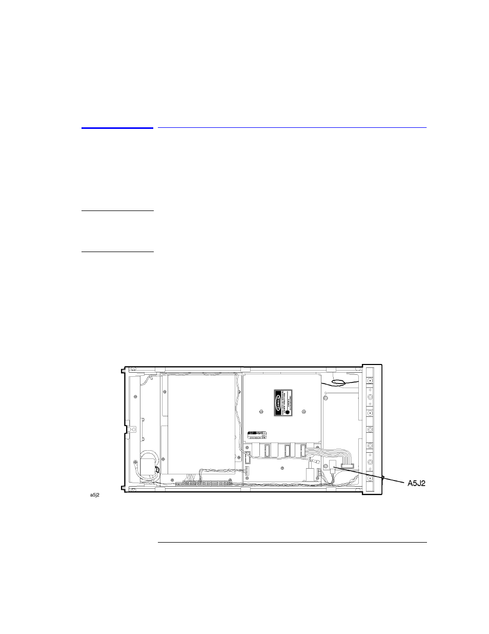
1
Remove the power supply cable from J2 on the A5 Laser Driver Board
Assembly. The end of this cable can be probed to measure all of the dc voltages
supplied in the assembly. The following list shows each wire color, its color
code, and its purpose:
• Red (2) wire: +15V
• White/red (92) wire: +5V
• Violet (7) wire: –15V
• Black (0) wire: ground
• White/black (90) wire: ground
2
Located the two indicator LEDs (green DS1 and yellow DS2) on the Laser
Driver Board Assembly.