Installation, 1400a – APC BC300 User Manual
Page 10
10
Installation Guide APC BC300 Series 60kW 208/480V UPS
990-1400A
Installation
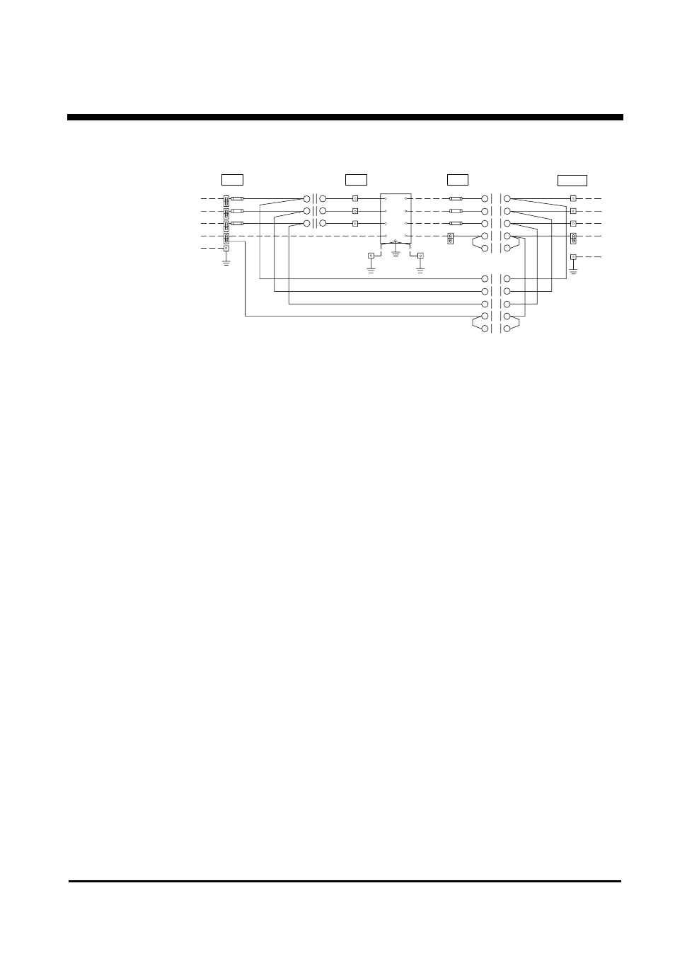
Figure 2 - SBP Electrical Schematic 208V & 480V
Notes:
1. 208V F1, F2, F3 = 175A
2. 480V F1, F2, F3 = 75A
3. 208V F4, F5, F6 = 250A
4. 480V F4, F5, F6 = 110A
5. All AC power cabling is 3- or 4-wire + Ground at 208VAC / 480VAC 3-phase.
6. Installation must comply with all applicable national and local codes.
7
3
U
11
15
19
20
16
12
8
4
U
U
U
U
Maintenance
Bypass Switch
Contacts marked "U"
closed in "UPS".
Contacts marked "BP"
closed in Bypass.
Contacts are Make
before Break.
AC Output
from UPS
F1
F2
F3
N
TO CRITICAL
LOAD CENTER
AC Output
to Critical Load
L1
L2
L3
N
G
L1
L2
L3
N
GRD
1
5
13
9
10
14
6
17
18
2
BP
BP
BP
BP
BP
G
G
Uninterruptible
Power Supply
L1
L1
L2
L2
L3
L3
N
N G
AC Input
to UPS
L1
L2
L3
UPS Input
Disc. Switch
Shown in Open
Position
1
2
4
6
5
3
AC Line
Input
F4
F5
F6
L1
L2
L3
N
GRD
- ROCK MOUNT 2200 (2 pages)
- 990-1387A (15 pages)
- 1500 (21 pages)
- VS 100 (65 pages)
- SMART-UPS 230VAC (1 page)
- Smart-UPS RT SURTA48XLBP (12 pages)
- SMARTUPS Smart-UPS 3000 (60 pages)
- BK400EI (40 pages)
- UPS control system (233 pages)
- 60-80kW (80 pages)
- Silcon DP300E Series (38 pages)
- 990-2902C (1 page)
- SILCON 990-4053 (76 pages)
- Step-Down Transformer AP9626 (10 pages)
- SMART-UPS 990-1841A (1 page)
- 600 (44 pages)
- 900XL (44 pages)
- 750VA (1 page)
- SMARTUPS Smart-UPS 2200 (2 pages)
- SMART-UPS 2200 (2 pages)
- SUA3000 (22 pages)
- 2200VA (25 pages)
- UPS (18 pages)
- SMART-UPS 990-7016B (2 pages)
- 208 Vac (24 pages)
- SU700RM2U (2 pages)
- Call-UPSII AP9208 (52 pages)
- ES 500 (2 pages)
- RS 500 (2 pages)
- 5000T (33 pages)
- Smart-UPS URTA48XLBPJ (12 pages)
- 420 (66 pages)
- SMART-UPS SUA2200 (22 pages)
- SYMMETRA SYCFXR9 (36 pages)
- SILCON 60-80KW 208/480V UPS (34 pages)
- MODULAR RACK-MOUNT POWER 990-3051C-001 (4 pages)
- SGI 15000 RAID (152 pages)
- Switched Rack Power Distribution Unit (PDU) (93 pages)
- SMART-UPS XL SUA48XLBP (9 pages)
- Smart-UPS VT (44 pages)
- 6000 VA (13 pages)
- NETBOTZ NBRK0200 (36 pages)
- GALAXY 5000 (68 pages)
- BC300 Series (38 pages)
- BR800I (2 pages)