Bosch HDI7052U User Manual
Page 13
13
Slide Range into Opening
1. Plug in power cord.
2. Slide range into opening, being careful not to
damage countertops, floors, or the range drawer
front. Do not apply pressure to cooktop when
sliding into position. Be careful not to crimp flex-
ible connector.
Tips:
1. If the range does not slide easily
Use soapy water to dampen the following
pressure points:
• countertop
• foam tape
• loor under range legs
2. Remove drawer and oven door to prevent
damage
3. To prevent damage to the appliance, push on
the frame around the oven cavity opening.
3. Wipe up soapy water.
Check Back of Range for Proper Installation
1. When properly installed, the cooktop trim around
the back of the range will rest lightly on the coun-
tertop.
2. There should not be any gap between the coun-
tertop and the trim; however, the weight of the
range must not rest on the countertop. Look
under the range to verify that both back legs are
resting solidly on the floor. Also verify that the left
range leg is under the anti-tip bracket.
Note: When replacing a free-standing model, the
backwall trim strip should be flush with the wall.
,
CAUTION
Verify that the weight of the range is not resting on
the countertop.
This could result in damage to the countertop and
the appliance.
3. If the back legs are not resting solidly on the
floor or the left leg is not under the anti-tip
bracket, slide range out, adjust legs and slide
back in.
Adjust Front of Range for Proper Installation
1. Adjust front leveling legs so that the cooktop trim
rests snugly against the countertop all the way
around.
2. Verify that both front legs are resting solidly on
the floor.
3. Use a level to verify that the range is level and
plumb.
4. Carefully tip range forward to ensure that anti-tip
bracket engages and prevents tip-over.
The gas connection is complete. Proceed to “Test
for Gas Leaks” on page 14.
Rigid Pipe Method
If using a flexible connector, return to “Flexible Con-
nector Method” on page 12.
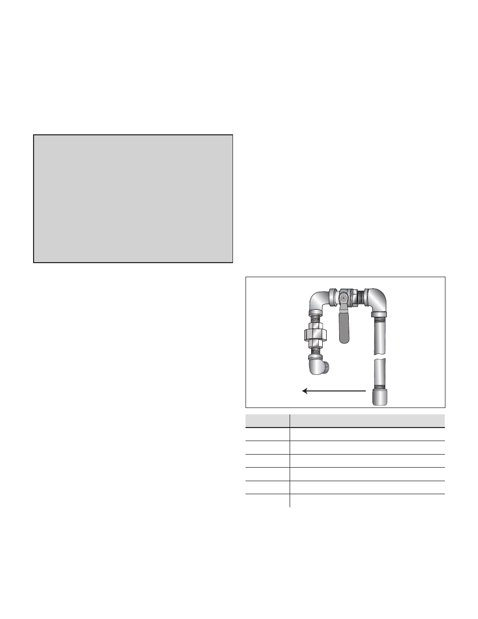
Attach Rigid Pipe
A
B
C
D
E
D
B
F
B
Gas Flow to Range
Letter
Item
A
Elbow; Connect to regulator here
B
Pipe Nipple
C
Union
D
Elbow
E
Gas Shut Off Valve
F
½" to ¾" Gas Pipe
The configuration of the rigid pipe connection will
vary depending on the location of the gas pipe stub.