2 cabling, Figure 13, Avis – ADC PWR-AVIS User Manual
Page 18
ADCP-61-814
•
Issue 1
•
April 1999
Page 14
© 1999, ADC Telecommunications, Inc.
OUT
CHASSIS GROUND
1
2
3
4
IN
6967-B
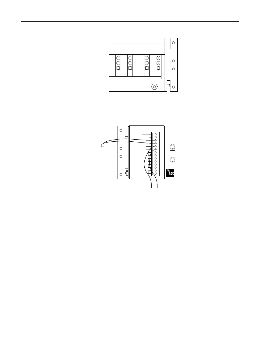
Figure 13. Chassis Ground Terminal
OUT
TEST
AVIS
IN
12248-B
SPARE
SPARE
–48V (1)
RET (1)
–48V (2)
RET (2)
PS1 ALM A
PS1 ALM B
PS2 ALM A
PS2 ALM B
CLASS 2
TO OFFICE
–48V FUSE
PANEL
TO 110 VAC TO
–48VDC CONVERTER
(OPTIONAL)
Figure 14. Office Power Connection
3.2 Cabling
Run and Cable the chassis as follows:
1. Obtain NE circuit IN and OUT assignments from local support staff.
2. Label all IN and OUT cables to identify NE associated with each card IN and OUT jack.
Ensure that the NE OUT cable terminates to the RIU OUT and the NE IN terminates to
the RIU IN.
3. Route the cables from the NE to the rear of the chassis.
Route circuits 1 through 10 on the right side of the rack, as viewed from the rear.
Route circuits 11 through 16 on the left side of the rack. See
.
- 310F (68 pages)
- HiGain H2TU-C-319 List 4E (88 pages)
- H4TU-C-319 List 1 Line Unit (79 pages)
- UTP Switchboard Cable (4 pages)
- FlexWave MMW 125 (4 pages)
- 600F (140 pages)
- Fibre ETSI Solution (8 pages)
- D3LXC-FCA100 (52 pages)
- 420F (106 pages)
- OmniReach OFDT-24 (4 pages)
- P-90-216 (15 pages)
- HiGain T1MF2S04RA (60 pages)
- TrueNet F/UTP Riser Cable (4 pages)
- UltraWAVE GSM Network-In-A-Box 105968AE (4 pages)
- InterReach 850 Cellular (12 pages)
- Soneplex Quad Loop Extender (2 pages)
- Digivance NXD (8 pages)
- Reliable (4 pages)
- GSM Base Station Controller UltraWAVE BSC (4 pages)
- UltraWAVE CDMA Pico BS Plus (2 pages)
- UniPatch GigE Series (4 pages)
- Cross-Connect DSXi (2 pages)
- OmniReach MDU Rapid Fiber System (8 pages)
- Baluns Series (5 pages)
- Universal Radio Head FlexWave (4 pages)
- Double Pair/Line Power G.SHDSL WorldDSL G.S (4 pages)
- FMT Drawers Featuring MicroVAM Modules (4 pages)
- SG-1 (226 pages)
- H2TU-C-388 (66 pages)
- TrueNet Rack Mount Fiber Enclosures RMG Series (8 pages)
- Universal Transport Platform for Access Networks PONy Express 16 (4 pages)
- TrueNet Augmented Category 6 Patch Cords (2 pages)
- 2 (44 pages)
- HiGain Wideband 3190 WBS-3190 (8 pages)
- TrueNet Termination Block (4 pages)
- Soneplex Broadband System (342 pages)
- LoopStar EtherNID (12 pages)
- Ethernet Distribution Frame TrueNet (2 pages)
- DSX-4R (RZX3) (2 pages)
- 24 AWG STC (4 pages)
- WMX 300 (4 pages)
- MM702G2 (134 pages)
- FlexWave MMX 8000 (4 pages)
- Fiber Optic Panel FL2000 Series (19 pages)