State GTS-240-NIH User Manual
Page 30
30
Page
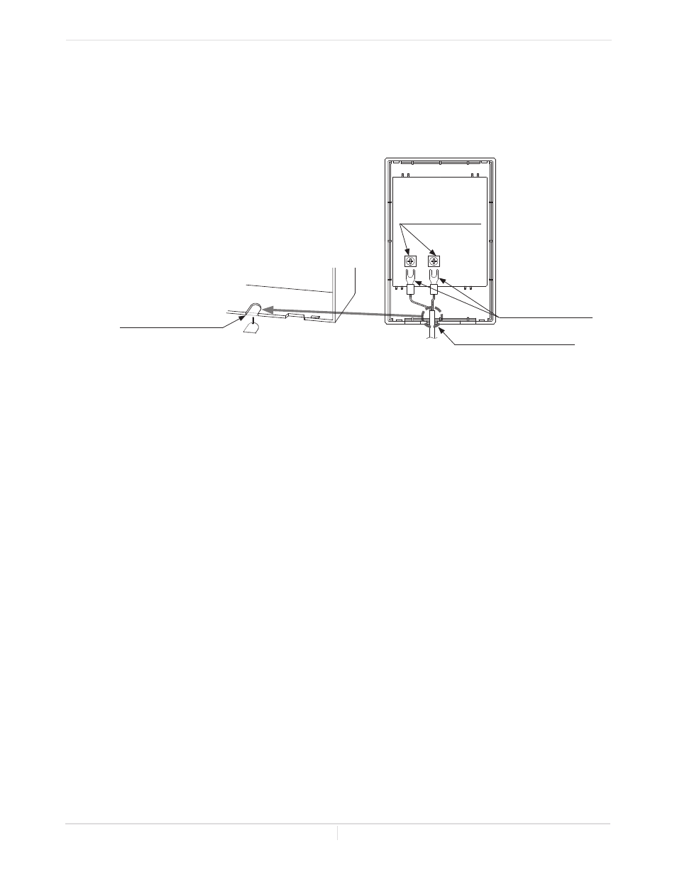
3. Tighten the two "Fork terminals" beneath the two "Remote controller terminal" screws on
the back of the main body. (Fig. C-1)
4. Cut out the inlet for the remote controller cable from the bottom of the main body. (Fig. C-2)
5. Place the “Main body” back on the "Back plate", with the "Remote controller cable" running
out of the bottom inlet.
1. Disconnect power supply from the water heater.
2. Take off the water heater’s front cover.
3. Locate the remote controller terminals, pictured to the next page (located around the lower
right-hand side of the computer board).
4. Take off the back plate from the remote controller, and then attach the two fork terminals to
connector base on the backside of the remote controller with two screws. Make sure the
terminals are firmly fixed.
5. Pull the remote’s wires through the hole at the bottom of the water heater’s casing.
6. Properly attach the remote’s wires to the remote controller terminal on the computer board
(No polarity).
* Do NOT jump or short-circuit the wires, or computer will be damaged.
7. Replace Front Cover securely.
8. Wires used for the remote controller connection must be:
• Minimum 20 gauge wire (No polarity)
• Maximum 400 ft. (122 m) long
Remote controller
terminals
Fig. C-1
Two fork terminals
Remote controller cable
Inlet for the remote
controller cable
Cut out
Fig. C-2
Installati on
Installati on Manual