Direct-vent and single vent illustrations, Installation installation manual – State GTS-240-NIH User Manual
Page 19
19
Page
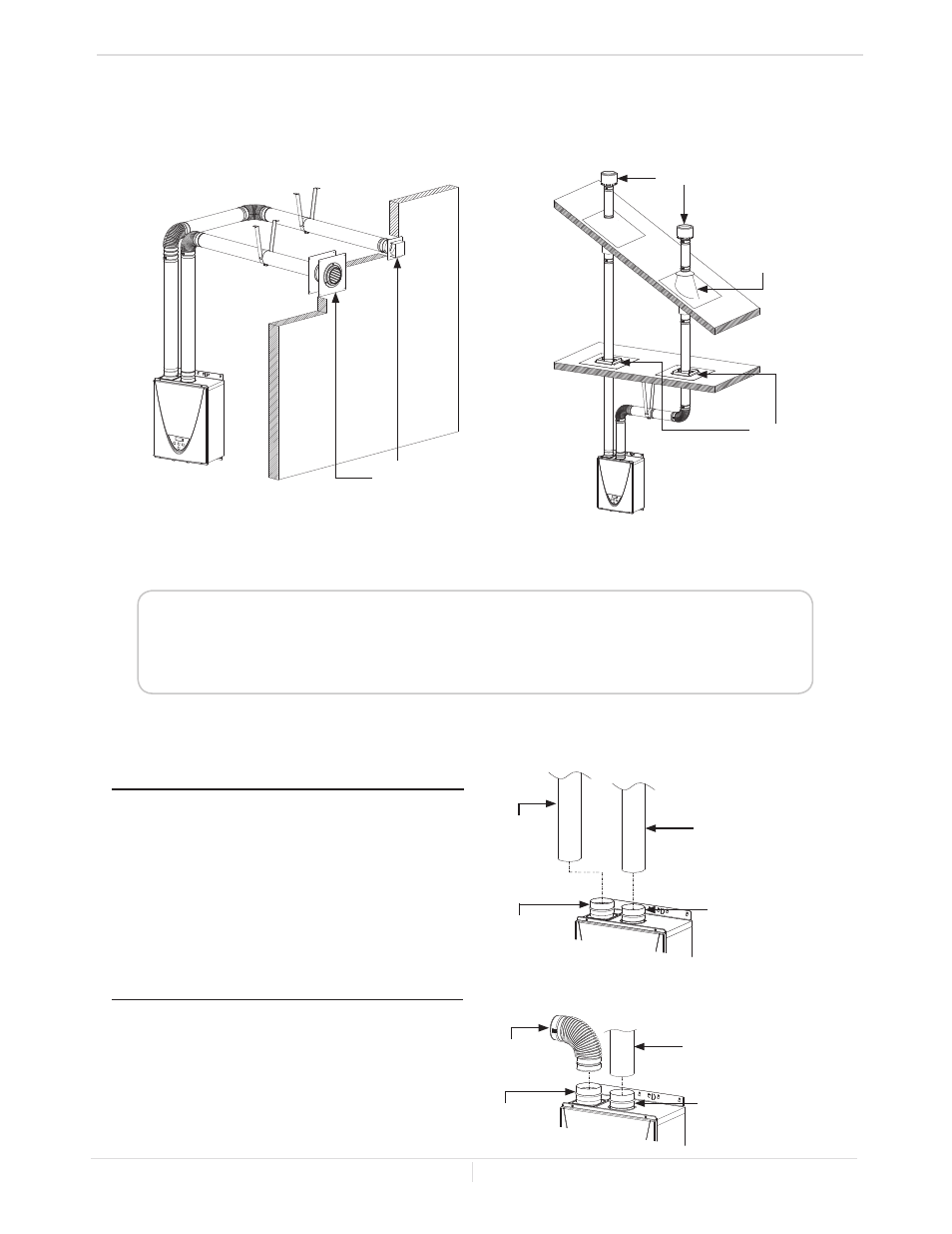
-Direct-vent and single vent Illustrations-
• Regarding the clearances from the exhaust terminal to the air inlet or opening, refer to the
next few pages.
• Follow all vent system manufacturer’s instructions and all local codes.
• Use 4” Category III/IV approved or Special BH, single or double wall stainless steel vent pipe.
Horizontal Installation
Wall
Sidewall vent
termination
Vertical Installation
Roof
Roof flashing
Fire stop
Rain cap
4" vent connection for direct-vent installation
4” stainless steel
vent straight pipe
Exhaust vent collar
of the Indoor models
(Female)
Intake vent collar
(Female)
4” stainless
steel vent
straight pipe
Installation
Installation Manual
Typical installations using stainless steel vents
Exhaust vent collar
of the Indoor models
(Female)
4” stainless steel
vent straight pipe
Intake vent collar
(Female)
4” elbow with
bird screen
1. Connect a 4" stainless steel vent
straight pipes directly on the
exhaust vent collar of the
water heater.
2. Connect a 4" elbow directly
on the intake vent collar of the
water heater.
1. Connect 4" stainless steel vent
straight pipes directly on the
exhaust/intake vent collar of the
water heater.
4" vent connection for single vent installation
• The diagram above shows direct-vent installations. For single vent installation, connect a 4" elbow
directly on the intake vent collar instead of a straight pipe. See the instructions below for the detail.
• For details of the optional items, refer to the Installation manual for each Optional item.