0 electrical installation – Setra System Model 224 User Manual
Page 3
2.4 Venting
Model 224 transducers are vented through the electronics housing.
3.0 ELECTRICAL INSTALLATION
3.1 Voltage Output Units
The Model 224 voltage output transducer is supplied with a 6ft. multiconductor
cable, Bayonet style connector, Mini Din connector, or D-Sub style connectors.
The voltage output is either 5 VDC FSO or 10 VDC FSO. Diagram 1 shows electrical
connection wiring for voltage output transducers, and the excitation required.
Diagram 1
Note:
Model 224 can be wired as a 3-wire device by connecting – OUTPUT and –EXCITATION and drain
wire to a common ground. However, accuracy may be reduced due to increase in resistance.
3.2 Current Output Units
The Model 224 is a two-wire loop-powered 4 to 20mA current output unit and
delivers rated current into any external load of 0-800 ohms. The Model 224 is
available with 6ft. of multiconductor cable, Bayonet, Mini Din, or D-Sub style
connectors. Diagram 2 shows electrical connection wiring for current output
transducers.
The power supply must be a DC voltage source with a voltage range between
10 VDC and 30 VDC measured between the + and - terminals. The unit is calibrated
at the factory with a 24 VDC loop supply voltage and a 250 ohm load.
Current must flow in one direction only - Please observe polarity. (See
Diagram 3.) We suggest that the cable shield Drain Wire be connected to the
system’s loop circuit ground for optimum electrical noise rejection. On transducers
with integral connectors (e.g., on Bayonet, D-sub, or MiniDin Connector types),
connection to transducer case ground can be achieved by connecting the cable
drain/shield wire to the mating cable-mounted connector shell (see Note 1).
Diagram 2
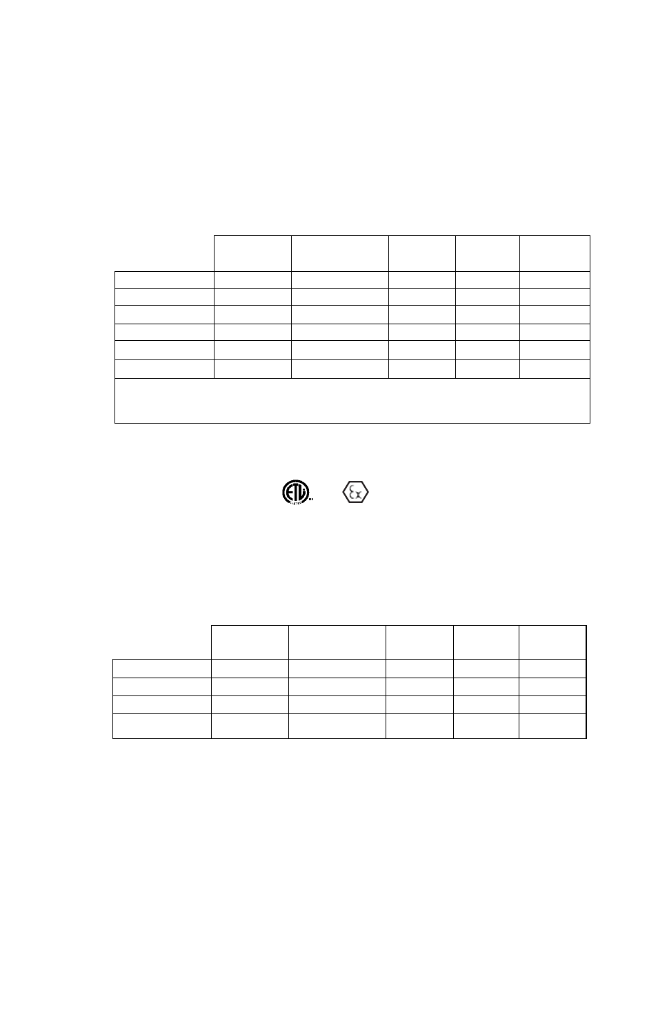
9 PIN
15 PIN
5 PIN
CABLE
BAYONET
D-SUB
D-SUB
MINI-DIN
CONNECTION
WIRE
PIN
PIN
PIN
PIN
+ EXCITATION
RED
A
4
7
1
+ OUTPUT
GREEN
B
1
2
2
– OUTPUT
WHITE
C
8
12
4
– EXCITATION
BLACK
D
9
5
5
CASE GND
DRAIN
SHELL
SHELL
SHELL
3
CONNECTOR PIN WIRING FOR VOLTAGE TRANSDUCERS
CONNECTOR PIN WIRING FOR CURRENT TRANSMITTERS
EXCITATION:
10-30 VDC FOR 0.2 TO 5.2 VDC and 0 to 5 VDC
13-30 VDC FOR 0.2 TO 10.2 VDC and 0 to 10 VDC
Minimum Supply Voltage = 10 + 0.02 x Loop Resistance
Maximum Supply Voltage = 30 + 0.004 x Loop Resistance
9 PIN
15 PIN
5 PIN
CABLE
BAYONET
D-SUB
D-SUB
MINI-DIN
CONNECTION
WIRE
PIN
PIN
PIN
PIN
+ EXCITATION
RED
A
4
7
1
– EXCITATION
BLACK
D & B
9
5
4
CASE GND
DRAIN
SHELL
SHELL
SHELL
3
3
and
w/N1 option, see Notes 2 and 3, Page 4.)
(