0 specifications, Table 1 configurable part number, Environmental – Setra System Model LD330 User Manual
Page 3: Electrical data, Model, Pressure range, Input, Pressure, Electrical connection to transducer, Electrical connection to power supply
LD 330V
LD 330C
Display
Voltage Input Display
Loop Powered Display
Digits
-999 to 1999
-999 to 1999
Type
7 Segment LCD, Green Backlight
7 Segment LCD
(Backlit Optional)
Polarity
Automatic (-) display
Automatic (-) display
Overload
1 followed by blank display
1 followed by blank display
Accuracy
0.25% of reading
±
1count
0.25% of reading
±
1 count
Environmental
Operating Temp.
32
°
F to 140
°
F (0C to 60C)
32
°
F to 140
°
F (0C to 60C)
Storage Temp.
-40
°
F to 158
°
F (-20C to 70C)
-40
°
F to 158
°
F (-20C to 70C)
Temp. Coeff.
100 ppm/C
100 ppm/C
Electrical Data
Input Signal
0.2 to 5.2 VDC
4-20 mA loop powered
Excitation
8 VDC to 30 VDC
4 VDC max voltage drop
300k ohm min input impedance
30 mA current consumption
3 mA with backlight disabled
At 32 VDC = 15 mA
Zero/Span Adjust
Multi-Turn potentiometers
Multi-Turn potentiometers
Protection
Reverse polarity protection
100 mA current limit
5.0 SPECIFICATIONS
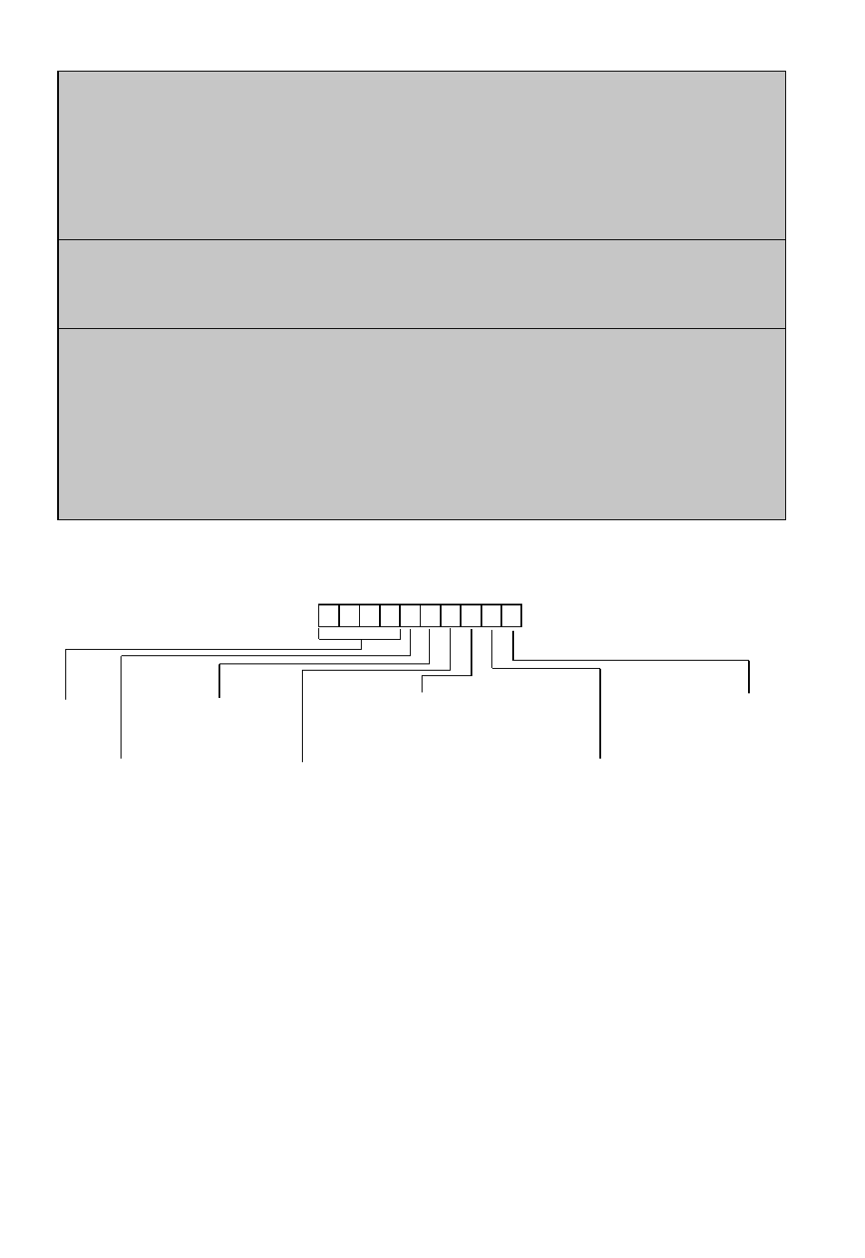
Example: Part No. 3301-V-3-C-B-T is a Model 330 with 0.2 to 5.2 VDC input, 100.0 pressure range, compound pressure,
Bayonet-Female-Bottom connection to transducer and a Bayonet-Male-Top connection to power supply.
TABLE 1 CONFIGURABLE PART NUMBER
3
Model
3301 = 330
Pressure Range
PSI Range
1 = 25.0
2 = 50.0
3 = 100.0
4 = 250
5 = 500
6 = 1000
7 = 3.00Kpsi
Bar Range
A = 1.70
B = 3.40
C = 7.00
D = 17.0
E = 34.0
F = 70.0
G = 210
Input
V
= 0.2 - 5.2 VDC
M
= 0-5 VDC
N
= 0.2 - 10.2 VDC
L
= 0-10 VDC
C
= 4-20 mA
B
= 4-20 mA
Backlit
Pressure
G = Gage
C = Compound
A = Absolute
Electrical Connection
to Transducer
B = Bayonet, Female, Bottom
R = Bayonet, Female, Rear
L
= Bayonet, Female, Lower Rear
H = Bayonet, Female, High Rear
M = Mini-Din, Rear
N = Mini-Din, Bottom
D = 15 Pin D-Sub, Rear
E = 9 Pin D-Sub, Bottom
F = Molex Rear
T = Bayonet, Male, Top
R = Bayonet, Male, Rear
C = 6ft. Cable, Rear
K = 6ft. Cable, Top
D = 15 Pin D-Sub, Bottom
E = 9 Pin D-Sub, Bottom
B = Bayonet, Male, Bottom
F = 1 ft. Cable, Top
J = 2 ft. Cable, Top
L = 3 ft. Cable, Top
U = 4 ft. Cable, Top
V = 5 ft. Cable, Top
W = 7ft. Cable, Top
1 = 1ft. Cable, Rear
2 = 2 ft. Cable, Rear
3 = 3 ft. Cable, Rear
4 = 4 ft. Cable, Rear
5 = 5 ft. Cable, Rear
7 = 7 ft. Cable, Rear
Electrical Connection
to Power Supply
Options
PN
= Panel Mount
(Panel Mount
is not
available for
4-20 mA
Backlit, Code B)
NONE
(leave blank)
for
Standard
Display