0 electrical installation, 1 current unit, Electrical connections are as follows – Setra System Model 299 User Manual
Page 2: Diagram 1 diagram 2 diagram 3, The model 299 (voltage input)
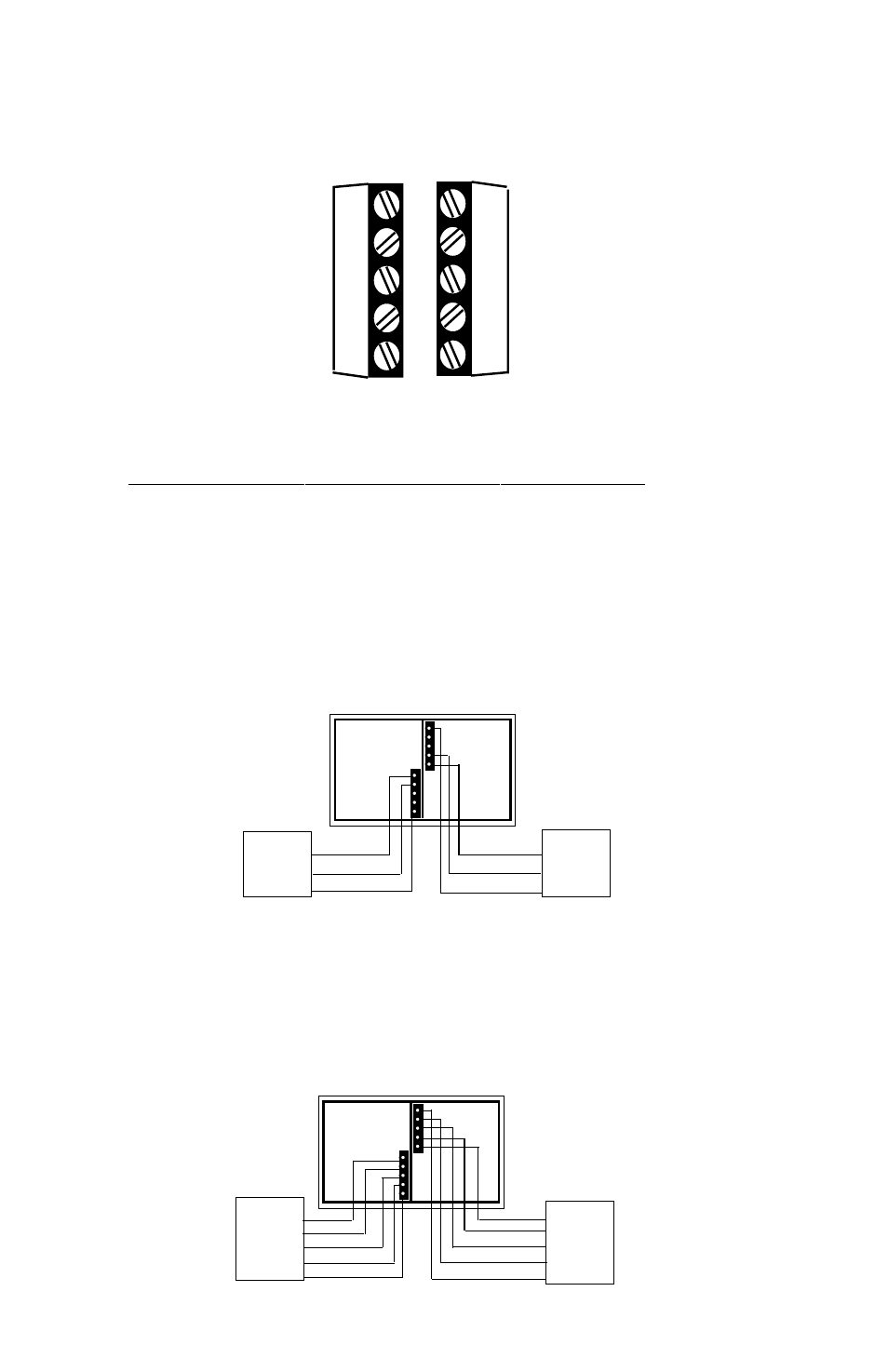
3.0 ELECTRICAL INSTALLATION
Wiring is through factory installed PG-9 Strain Reliefs. Wiring terminations are
identified below the terminals (Diagram 1).
NOTE: Prep Transducer and Data Acquisition Wires Prior to Wiring to the 299: Strip transducer
cable back to expose wires and capillary vent tube. Tube should remain free and not crimped or
pinched. Strip data acquisition cable to expose wires. CAUTION: Overtightening of the PG9 Strain
Reliefs may pinch tube and cables.
3.1 Current Unit
The Model 299 (current input) - Reverse polarity protected when used with a
Setra pressure transducer.
The electrical connections are as follows:
3.2 Voltage Unit
The Model 299 (voltage input)
electrical connections are as follows:
Model 299
Setra Termination Enclosure
(Voltage Input)
Pressure
Transducer
+
+
_
out
out
GRND
_
Data
Acquisition
System
+
+
_
out
GRND
out
_
exc.
exc.
_
+
_
+
+
exc.
exc. _
_
+
GRND
GRND
GRND
Model 299
Setra Termination Enclosure
(Current Input)
Pressure
Transducer
+
+
_
exc.
exc.
GRND
_
Data
Acquisition
System
+
+
_
exc.
GRND
exc.
_
GRND
-
Diagram 1
Diagram 2
Diagram 3
-
+
-
+
GRND
Out
Out
Exc
Exc
GRND
Out
Out
+
Exc
Exc
-
+