0 electrical installation – Setra System Model 217 User Manual
Page 3
3
Note:
Model 217 can be wired as a 3-wire device by connecting
– OUTPUT and –EXCITATION and drain wire to a common ground. However, accuracy may be reduced due
to increase in resistance.
3.2 Current Output Units
The Model 217 is a two-wire loop-powered 4 to 20mA current output unit and
delivers rated current into any external load of 0-800 ohms. The Model 217 is
available with 6ft. of multiconductor cable, Bayonet style connector, Mini Din
or D-Sub style connectors. Diagram 3 shows electrical connection wiring
for current output transducers.
The power supply must be a DC voltage source with a voltage range between
10 VDC and 30 VDC measured between the + and - terminals. The unit is
calibrated at the factory with a 24 VDC loop supply voltage and a 250 ohm load.
Current must flow in one direction only - Please observe polarity. (See
Diagram 4.) We suggest that the cable shield Drain Wire be connected to the
9 PIN
15 PIN
5 PIN
CABLE
BAYONET
D-SUB
D-SUB
MINI-DIN
CONNECTION
WIRE
PIN
PIN
PIN
PIN
+ EXCITATION
RED
A
4
7
1
– EXCITATION
BLACK
D & B
9
5
4
CASE GND
DRAIN
SHELL
SHELL
SHELL
3
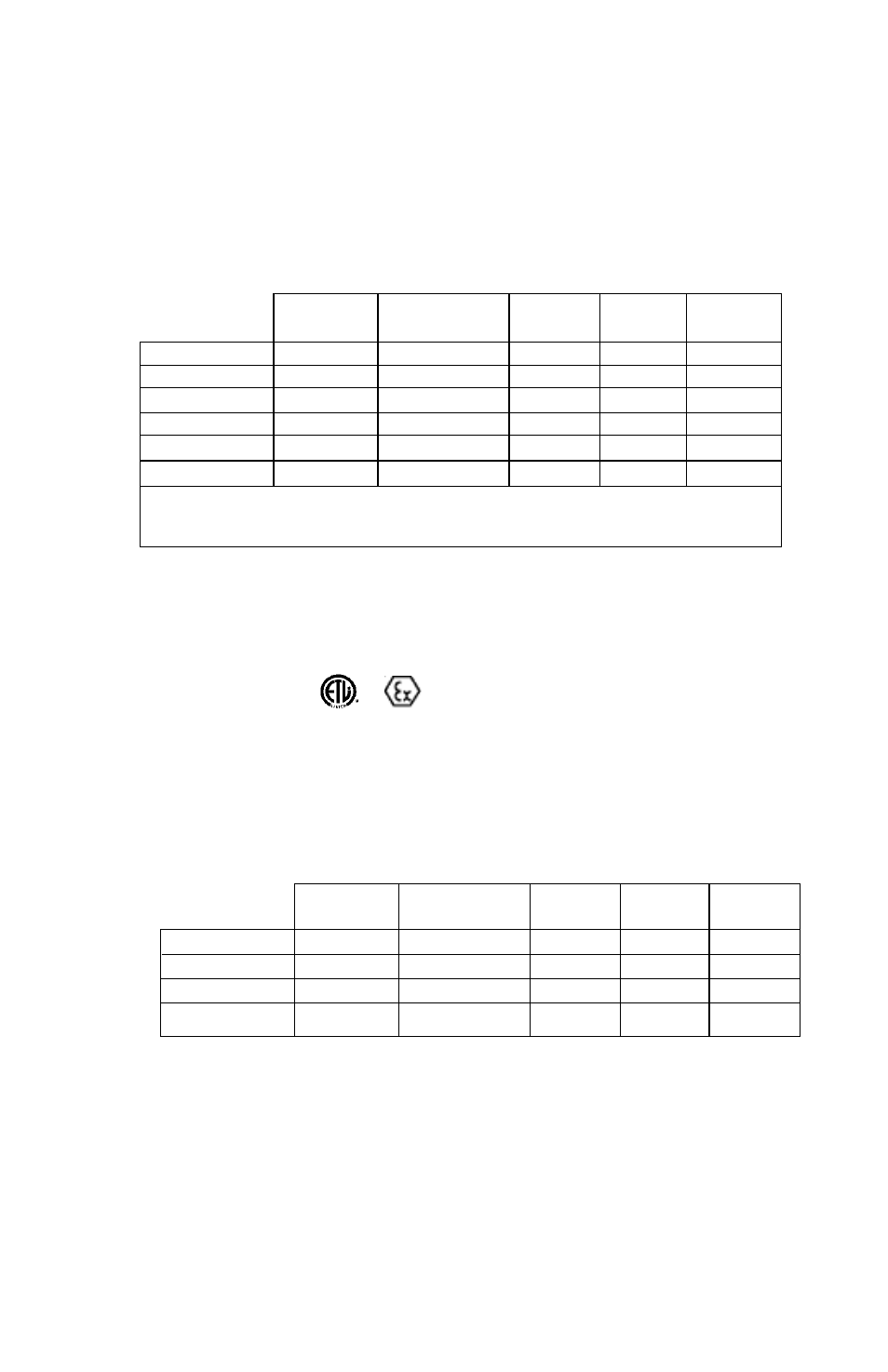
3.0 ELECTRICAL INSTALLATION
3.1 Voltage Output Units
The Model 217 voltage output transducer is supplied with a 6ft. multiconductor cable, Bayonet style connector,
Mini Din connector or D-Sub style connectors. The voltage output is either 5 VDC FSO or 10 VDC FSO.
Diagram 2 shows electrical connection wiring for voltage output transducers, and the excitation required.
Diagram 3
CONNECTOR PIN WIRING FOR CURRENT TRANSMITTERS
Minimum Supply Voltage = 10 + 0.02 x Loop Resistance
Maximum Supply Voltage = 30 + 0.004 x Loop Resistance
9 PIN
15 PIN
5 PIN
CABLE
BAYONET
D-SUB
D-SUB
MINI-DIN
CONNECTION
WIRE
PIN
PIN
PIN
PIN
+ EXCITATION
RED
A
4
7
1
+ OUTPUT
GREEN
B
1
2
2
– OUTPUT
WHITE
C
8
12
4
– EXCITATION
BLACK
D
9
5
5
CASE GND
DRAIN
SHELL
SHELL
SHELL
3
Diagram 2
CONNECTOR PIN WIRING FOR VOLTAGE TRANSDUCERS
EXCITATION:
10-30 VDC FOR 0.2 TO 5.2 VDC and 0 to 5 VDC
13-30 VDC FOR 0.2 TO 10.2 VDC and 0 to 10 VDC
and
( w/N1 option, see Notes 2 and 3.)