Setra System Model 542 User Manual
Page 6
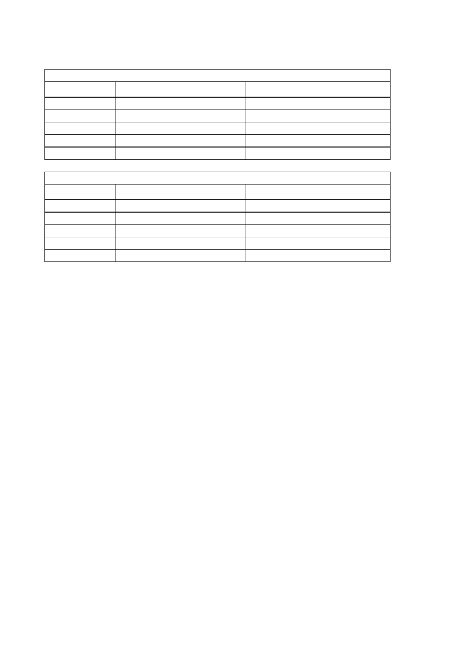
Compensated Temperature Range
Model
Electrical Connector
Temperature
540 / 542
10-6 Bayonet Connector
-65°F to +250°F (-54°C to +120°C)
541
10-6 Bayonet Connector
-65°F to +390°F (-54°C to +200°C)
540 / 542
Weatherproof Cable
-65°F to +250°F (-54°C to +120°C)
540 / 542
Molded Immersible Cable
-65°F to +250°F (-54°C to +120°C)
541
10-5 Screw Lock Connector
-65°F to +390°F (-54°C to +200°C)
Operating Temperature Range
Model
Electrical Connector
Temperature
540 / 542
10-6 Bayonet Connector
-65°F to +275°F (-54°C to +135°C)
541
10-6 Bayonet Connector
-65°F to +385°F (-54°C to +195°C)
540 / 542
Weatherproof Cable
-65°F to +250°F (-54°C to +120°C)
540 / 542
Molded Immersible Cable
-4°F to 122°F (-20°C to +50°C)
541
10-5 Screw Lock Connector
-65°F to +450°F (-54°C to +230°C)
OPERATIONAL LIFE:
Limited to 100M cycles to maximum allowable pressure.
CALIBRATION
Transducers are calibrated to the datum requested at time of order; this can be identified as follows:-
Code G - gauge datum vented to atmosphere via the electrical connection
Code A - absolute datum
Code S - sealed reference; reference side of the instrument is sealed and the output electrically adjusted
to zero with 1013 mb applied to pressure port
Code U - uni-directional differential
Code B - bi-directional differential
CHARACTERISTICS
Millivolt Output Transducers: All millivolt (mV) output transducers should be used with a
stabilized d.c. excitation supply. Output errors directly proportional to supply instability.
Specifications are given with 10V d.c. excitation. However, a lower supply may be used with a
corresponding decrease in output.
There are no adjustments for zero and span on the transducer. If local provision is required, the circuit
diagram below may be employed. 12V d.c. stabilized supply is used instead of standard 10V to allow
span adjustment to be obtained.