Calibration, 1 zero/span adjustments with security key, 2 zero adjustment (current output) – Setra System 269 User Manual
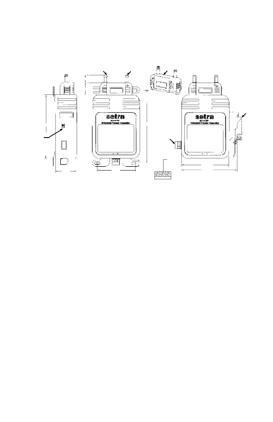
Page 2: 3 span adjustment (current output), 4 turn down adjustment (option), Diagram 1
2
4.0. CALIBRATION
The 269 transducer is factory calibrated and should require no field adjustment if mounted in a vertical position.
Whenever possible, any zero and/or span offsets should be corrected by software adjustment in the user’s control
system. However, fine zero and span adjustments can be made thru a calibration secure access key. The Model 269
transducer zero offset is trimmed in the vertical position (pressure ports pointing upward) prior to shipping from
factory.
4.1 Zero/Span Adjustments with Security Key
To make secure zero and span adjustments, remove detachable process head by pressing and pulling on side tabs.
Install calibration security key in-place of process head. (See Diagram 3).
4.2 Zero Adjustment (Current Output)
While applying zero differential pressure, zero may be adjusted by pressing the cal button to tare zero. If fine adjust-
ment is needed on analog output, depress cal button while turning the encoder.
4.3 Span Adjustment (Current Output)
Span or full scale output adjustments should only be performed by using an accurate pressure standard (electronic
manometer, digital pressure gauge, etc.) with at least comparable accuracy to the 269 transducer. With full range pres-
sure applied to the high pressure port (reference port open to atmosphere), the span may be adjusted by pressing the
cal button to set span. If fine adjustment is needed on span, and control pressure is applied at least 75% of full range,
turn encoder until target output is achieved.
4.4 Turn Down Adjustment (Option)
For units with optional turn-down gain, turn down is easily adjusted through use of slider switch located on side of
unit. (See Diagram 1)
The current flows into the + terminal and returns back to the power supply through the - terminal (See Diagram 2).
The power supply must be a DC voltage source with a voltage range between 13.5 and 30 measured between
the + and - terminals. The unit is calibrated at the factory with a 24 VDC loop supply voltage and a 250 ohm load.
3.90”
2.35”
1.30”
.48”
Low Pressure Port
High Pressure Port
4.50”
Detachable Process
Head
Detachable
Electrical
Connector
2.90”
3.70”
Din
Rail
Shield
to
Ground
- +
Turn-Down
Switch
Diagram 1