1 voltage output zero adjustment – Setra System Model 227 User Manual
Page 4
should be adjusted with the unit at atmospheric pressure and the
output adjusted as noted in Diagrams 5 & 6 on pages 4 & 5. Zero and span
adjustments can be made by turning the rotatable access cover to expose
the zero and span potentiometers. Be certain to close the rotatable cover after
adjustments are made.
4.1 Voltage Output Zero Adjustment
While monitoring the voltage between the positive output (+OUT) and
common (COM), with the pressure port open to atmosphere or with zero
pressure applied, the zero may be adjusted by turning the zero potentiom-
eter screw.
For the 5 VDC Full Scale Output, the tolerance on zero and span settings is
±25mV. For the 10 VDC Full Scale Output, the tolerance on zero and span
settings is
±50mV. For absolute pressure ranges, the zero and span should be
adjusted with a full vacuum applied. See Diagram 5 below for nominal
“installed” output at atmospheric pressure for compound pressure ranges.
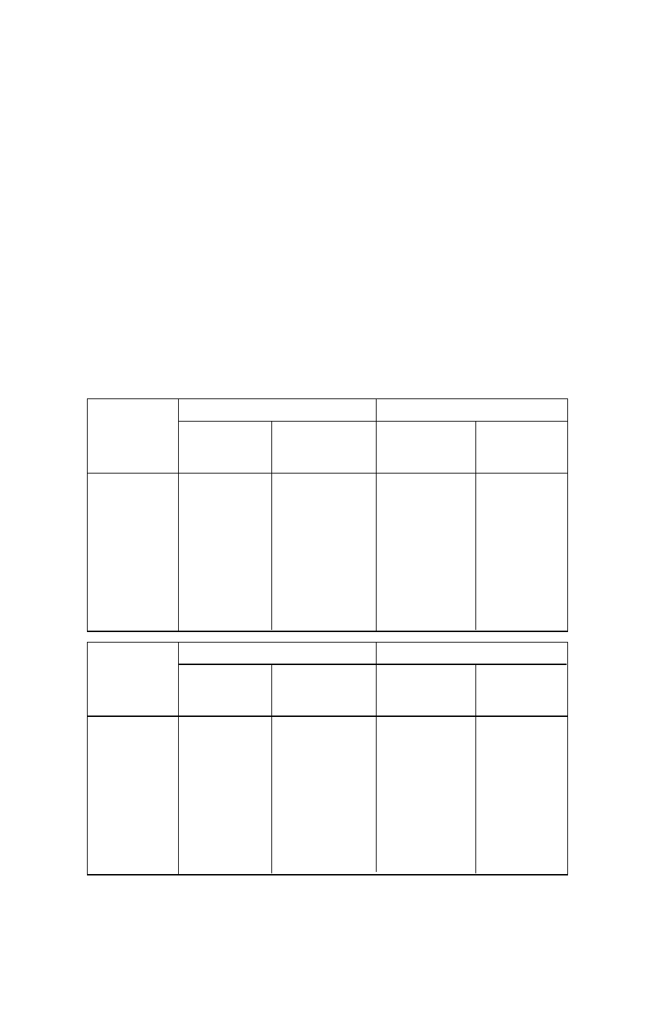
NOMINAL “INSTALLED” OUTPUT AT ATMOSPHERIC PRESSURE
Diagram 5
PSI
5 VDC Full Scale Outputs
10 VDC Full Scale Outputs
Compound
0.2 to 5.2
0 to 5 VDC
0.2 to 10.2
0 to 10 VDC
Range
Voltage (VDC)
Voltage (VDC)
Voltage (VDC)
Voltage (VDC)
-14.7 to 25
2.051
1.851
3.903
3.703
-14.7 to 50
1.336
1.136
2.472
2.272
-14.7 to 100
0.841
0.641
1.482
1.282
-14.7 to 250
0.478
0.278
0.755
0.555
-14.7 to 500
0.343
0.143
0.486
0.286
-14.7 to 1000
0.272
0.072
0.345
0.145
-14.7 to 3000
0.224
0.024
0.249
0.049
Bar
5 VDC Full Scale Outputs
10 VDC Full Scale Outputs
Compound
0.2 to 5.2
0 to 5 VDC
0.2 to 10.2
0 to 10 VDC
Range
Voltage (VDC)
Voltage (VDC)
Voltage (VDC)
Voltage (VDC)
-1 to 1.7
2.052
1.851
3.904
3.704
-1 to 3.4
1.336
1.136
2.473
2.273
-1 to 7
0.825
0.625
1.450
1.250
-1 to 17
2.494
0.278
0.756
0.556
- 1 to 35
0.339
0.139
0.478
0.278
-1 to 70
0.270
0.070
0.341
0.141
-1 to 200
0.225
0.025
0.250
0.050
4