3 making a single-axis measurement, Making a single-axis measurement, Table 5-2: sam axis select bits – PNI RM3000-F Evaluation Board User Manual
Page 16
PNI Sensor Corporation
Doc #1016391 r04
RM3000-f Evaluation Board User Manual
Page 15
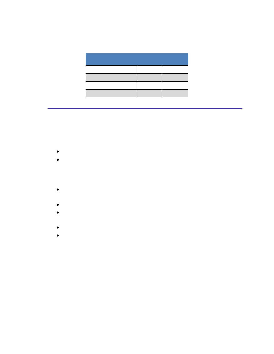
Table 5-2: SAM Axis Select Bits
Description
AS1
AS0
No axis measured
0
0
X axis (Channel 1)
0
1
Y axis (Channel 2)
1
0
Z axis (Channel 3)
1
1
5.2.3 Making a Single-Axis Measurement
The steps to make an interrupt-driven single-axis sensor measurement are given below.
The 3D MagIC will return the result of a complete forward-reverse measurement of the
sensor in a 24-bit 2’s complement format (range: -8388608 to 8388607).
SSN pin is set LOW. This enables communication with the master device.
The SAM Command Byte is clocked into the 3D MagIC on the MOSI pin.
Simultaneously, the 3D MagIC will present a fixed 0x9A on the MISO pin. Once
the 8 bits have clocked in, the 3D MagIC will execute the command (i.e. take a
measurement).
The SSN input may be returned HIGH at this point to free up host communication
with another device if desired. This will not affect the measurement process.
A measurement is taken.
At the end of the measurement, the DRDY pin is set HIGH, indicating data is
ready, and the 3D MagIC is placed in Idle Mode.
The SSN input should be set LOW, if it is not already, to read the data.
The data is clocked out on the MISO pin with the next 24 clock cycles.
If another measurement is immediately made, SSN can remain LOW and the process
repeated. Otherwise it is recommended that SSN is set HIGH to release the SPI bus.