4 idle mode, Idle mode, Figure 4-1: spi timing diagram – PNI RM3000-F Evaluation Board User Manual
Page 12: Table 4-2: spi timing specifications, Figure 4-1, In table 4-2)
PNI Sensor Corporation
Doc #1016391 r04
RM3000-f Evaluation Board User Manual
Page 11
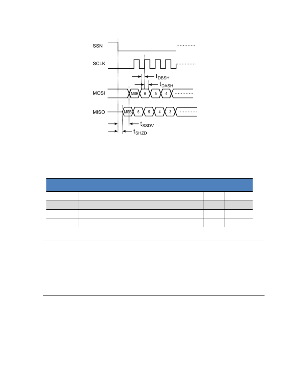
Figure 4-1: SPI Timing Diagram
Table 4-2: SPI Timing Specifications
Symbol
Description
Min
Max
Units
t
SSDV
Time from SSN to Command Byte on MOSI
1
us
t
DBSH
Time to setup data before active edge
50
ns
t
DASH
Time to setup data after active edge
50
ns
t
SHZD
Time from SSN to data tri-state time
100
ns
4.4 Idle Mode
The RM3000-f Evaluation Board incorporates an Idle Mode to reduce power consumption, in
which the circuit automatically idles when it is not exchanging data or taking a measurement.
The RM3000-f Evaluation Board starts in the Idle Mode at power-up and remains in Idle
Mode until a measurement is needed.
Note: The fact that the RM3000-f Evaluation Board starts in Idle Mode at power-up is different from
the legacy MicroMag modules, where it was necessary to cycle the MicroMag modules through one
measurement-request operation at power-up to put them into Idle Mode.