R/w: read/write, Adr0 – adr3: register address bits, Table 5-1: cycle count register commands – PNI RM3000-F Evaluation Board User Manual
Page 14
PNI Sensor Corporation
Doc #1016391 r04
RM3000-f Evaluation Board User Manual
Page 13
be repopulated unless the user wants to change the values or the system is powered down (in
which case the default values would populate the register fields when powered up again).
See the
for code examples, including how to set the cycle count registers.
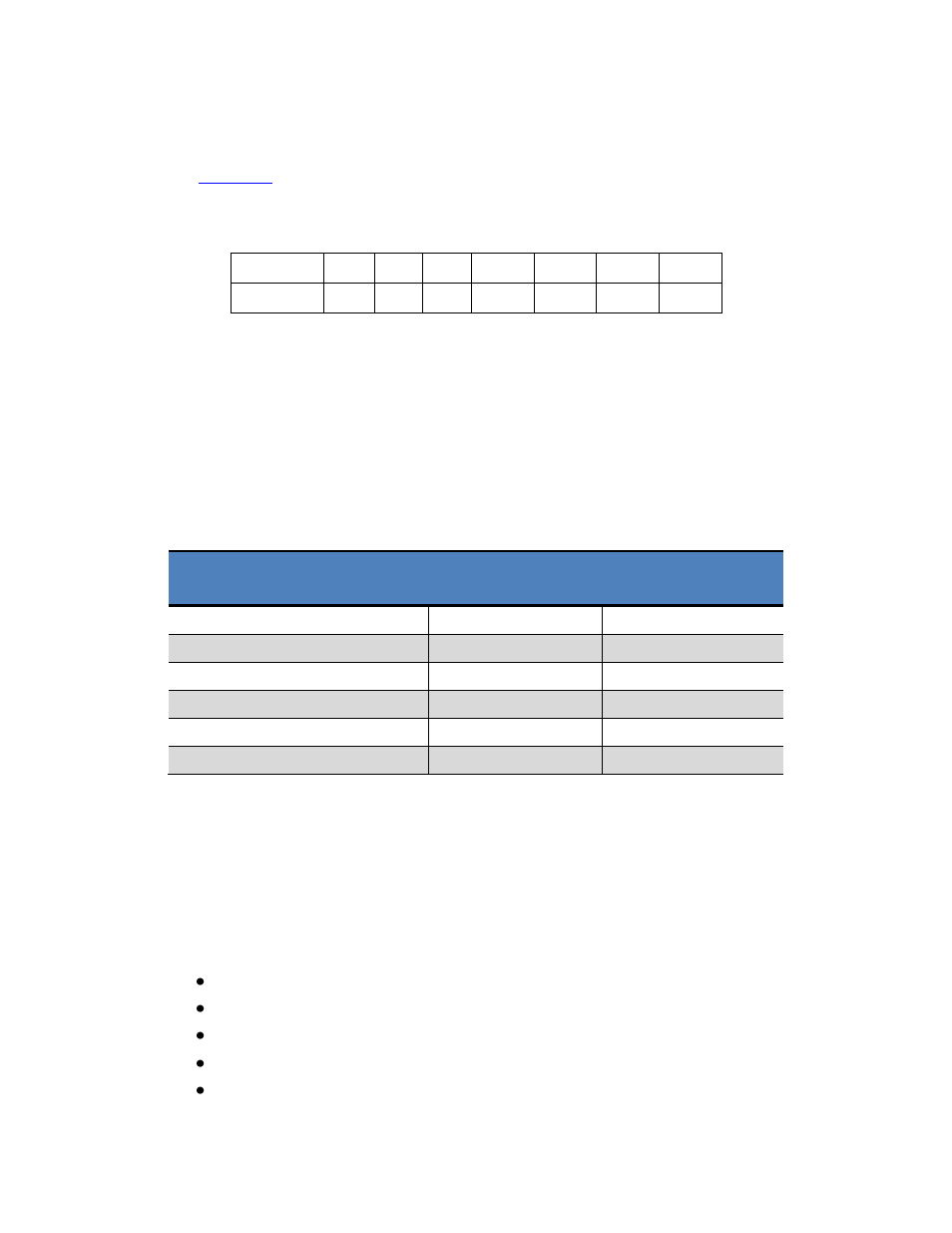
To initiate a read or write from the Cycle Count Register, send the Command Byte:
7
6
5
4
3
2
1
0
RFLAG=1 R/W
0
0
ADR3 ADR2 ADR1 ADR0
R/W: Read/Write
HIGH signifies a Read from the addressed register. LOW signifies a Write operation.
ADR0
– ADR3: Register Address Bits
Establishes which register will be written to or read from. Each sensor is represented
by two registers, with addresses defined as follows:
Table 5-1: Cycle Count Register Commands
Register Description
Read Command
Byte
Write Command
Byte
X Axis Cycle Count Value - MSB
C3H
83
H
X Axis Cycle Count Value - LSB
C4
H
84
H
Y Axis Cycle Count Value - MSB
C5
H
85
H
Y Axis Cycle Count Value - LSB
C6
H
86
H
Z Axis Cycle Count Value - MSB
C7
H
87
H
Z Axis Cycle Count Value - LSB
C8
H
88
H
Since the registers are adjacent, it is not necessary to send multiple Command Bytes, as the
RM3000-f Evaluation Board automatically will read/write to the next adjacent register.
A sample command sequence is provided below which sets the cycle count value to 100
D
(64
H
) for all 3 axes. This is purely for illustrative purposes and the value could be different
and/or the number of axes to be addressed could be different.
Start with SSN set HIGH, then set SSN to LOW.
Send 0x83 (this is the Write Command Byte to address the MSB for the X axis)
Send 0x00 (value for the MSB for the X axis)
Send 0x64 (value for the LSB for the X axis - pointer automatically increments)
Send 0x00 (value for the MSB for the Y axis - pointer automatically increments)