Hardware setup, Figure 4-1: commboard configuration block diagram, Figure 4-2: commboard signal and power connections – PNI CommBoard User Manual
Page 8: 2 hardware setup
PNI Sensor Corporation
DOC#1018122 r02
PNI CommBoard User Manual
Page 6
Figure 4-1: CommBoard Configuration Block Diagram
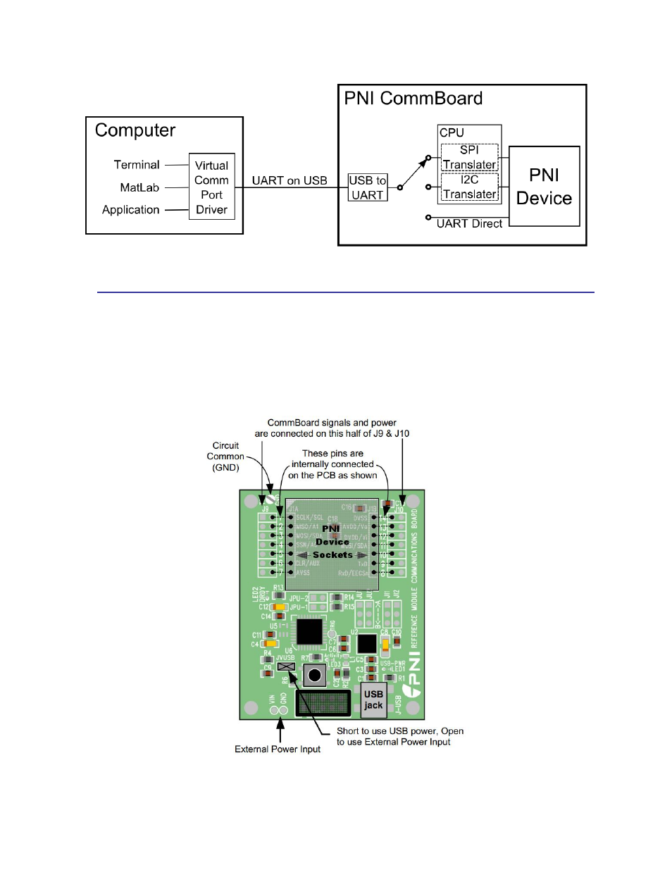
4.2 Hardware Setup
Figure 4-2 indicates where power connections can be made to the CommBoard, and also
where the signal lines are connected. For most users, the power and signal lines will be
supplied via the mini-USB jack. Next configure the jumpers on the CommBoard to match
your device, as illustrated in Figure 4-3.
Figure 4-2: CommBoard Signal and Power Connections