NORD Drivesystems Berges-VG User Manual
Page 24
6.2.3
Changing the variable-speed pulleys
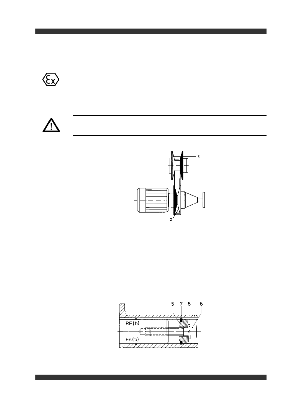
Installing the variable-speed and spring pulley ( Figure 12 )
The pulley bores are manufactures to DIN 7154, fit H7. The dimensions of the spli -
nes comply with DIN 6885, Sheet 1 (3) and the tolerance also complies with fit H7.
The variable - speed pulleys must be fitted on the drive and output shafts with a sli -
ding fit (do not use force, e.g. by hammering).
Never fit too tight since, otherwise, the main hub would expand in the bore and
prevent the sliding pulley halves ( 2 and 3 ) sliding.
Caution!
The moving pulley halves ( Items 2 and 3 ) of both variable - speed pulleys must
always be diagonally opposed. ( See Figure 12 )
Figure 12
Axial locking of the variable-speed pulleys ( Figure 13 )
The pulleys must be mounted as shown in Figure 13. This type of mounting affords
two essential advantages:
- there are no rotating parts projecting outside of the pulley
- the attachment system also be used as an extractor device. ( see Figure 14 )
The attachment discs ( Item 5 ) are designed in accordance with Works Standard in
line with the threads in the drive and output shafts to DIN 332 - Sheet 2.
Figure 13
24
Servicing