3 connection of the rev-counter, Installation – NORD Drivesystems Berges-VG User Manual
Page 17
1
2
3
4
5
6
4.4.3
Connection of the rev-counter
The electrical rev-counter is an option and can be retrofitted at any time. The rev -
counter is supplied with a connection cable. This is connected user-specifically - if
using an indicator provided by the customer - or in accordance with the regulations
for the BERGES indicator.
Pulse encoder
The rotational speed is measured without physical contact using a rotating perforated
disc which simultaneously serves to secure the spring pulley and stationary pulse
encoder.
The pulse encoder generates a digital signal in conjunction with a NAMUR input.
Suitable BERGES indicators:
Technical Data pulse encoder:
Digital indicator unit DVM 120 D1
Housing
High-grade steel, stainless
- for supply voltage 24V-DC / 230V-AC
Connection -
2m PVC-cable 2x0.14
Digital indicator unit DA4 / EX- 40
cable *
2x 0,34mm
2
- for supply voltage 24V-DC / 230V-AC
Contr. circuits
DIN 19234 resp. Namur
in connection with a isolating transformer and
Rated voltage
10V
a frequency current transformer.
Sensing dist.
0......1,62 mm
Analogue indicator FFA 96
EMV to
EN 60947 - 5 - 2
- for supply voltage 24V-DC / 230V-AC
* with angle connector
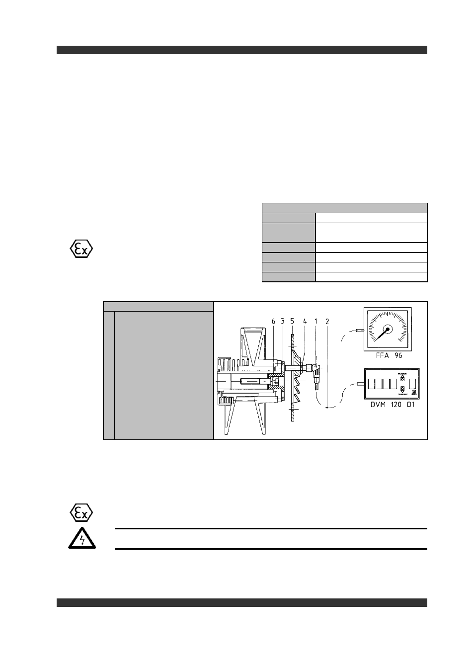
Figure 8 Pulse encoder
Pulse encoder
Connection cable 2m
( optionally 5m )
Perforated disc
Securing nut
( incremental encoder )
Fan cover
Securing screw
(perforated disc a.Fpulley )
1. Insert the collar of the perforated disc
( Item 3 )
into the bore of the spring pulley
and secure it with the securing screw ( Item 6 ) in the output shaft.
2. Screw the pulse encoder
( Item 1 )
into the ventilation cover
( Item 5 ).
3. Set the measuring gap: Screw the pulse encoder
( Item 1 )
fully against the per-
forated disc
( Item 3 ) ,
turn it back one turn ( sensing distance approx. 1 mm )
and lock with the nut ( Item 4 ) with respect to the ventilation cover ( Item 5 ).
4. Pulse meter to be turned back 2 revolutions (clearance distance about 2 mm)
Caution !
Ensure that the pulse encoder ( Item 1 ) is not screwed into a bore in the
perforated disc.
4. Install the indicator and connect it as shown in the connection diagram.
5. Adjust the reading: ( see separate Operating Instructions supplied with the
indictor ).
17
Installation