Installation – NORD Drivesystems Berges-VG User Manual
Page 16
4.4.2
Connection of the electrical remote control motor
Stop!
The motor of the electrical remote control may be operated only with the main motor
operating.
1. Connect the motor in accordance with the circuit diagram (Figure 7).
2. Check the direction of rotation in inching mode:
- Briefly press button S1; the operating pin must move towards the bolt-on flange.
- Briefly press button S2; the operating pin must move in the opposite direction.
- If the directions are incorrect, reverse the polarity of the motor.
3. Checking the function of the limit switches:
- Acutate limit switch S3 ( n
2 max
) and briefly press button S1.
- Acutate limit switch S4 ( n
2 min
) and briefly press button S2.
- The operating pin may not move in either of the two cases.
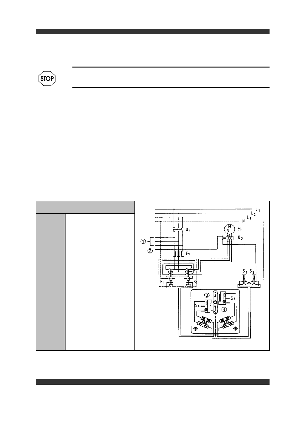
Figure 7
Connect.diagr.for electr.remote control
F1
Fuse
K1, K2
Combined switching contactor
for pha.reversal ( clockwise or
counter clockwise rotation of
the motor )
M1
Motor
Q1
Master switch
Q2
Motor protection switch
S1
Pushbutton switch "Faster"
S2
Pushbutton switch "Slower"
S3
Limit switch
( upper speed limitation )
S4
Limit switch
( lower speed limitation )
1
Drive motor ( main motor )
2
Control phase of drive motor
3
faster
4
slower
16
Installation