Configuration, Broadcast mode – NORD Drivesystems TI 275281206 User Manual
Page 7
IO-Extension
– SK TU4-IOE-M12
TI 275281206 - 4912
7
Pos : 13 /T echnisc he I nf ormati onen/I O - Er weit er ung/ Konfigur ati on [I OE Allgemein] @ 2\ mod_1352388400441_388. doc x @ 50928 @ 6 @ 1
Configuration
Configuration of the module is mainly performed via the DIP switches. The DIP switches are read after
a "power on" of the module. A change to the DIP switch during operation has no effect.
The system bus must be terminated at both of its physical ends (if necessary set the "System bus
termination resistor" DIP switch).
Note
Broadcast mode
In "Broadcast mode, which is activated via the parameter (P162), the module can access up to 4 inverters in
parallel. Therefore the frequency inverters jointly access the I/Os and evaluate the input signals according to their
own parameterisation. Output signals from the frequency inverters which are sent to the common IO module are
linked by a logical "OR" within the module. i.e. a digital output is set as soon as one of the four frequency inverters
addresses it. In addition, the highest analog value is provided via the analog output of the IO extension.
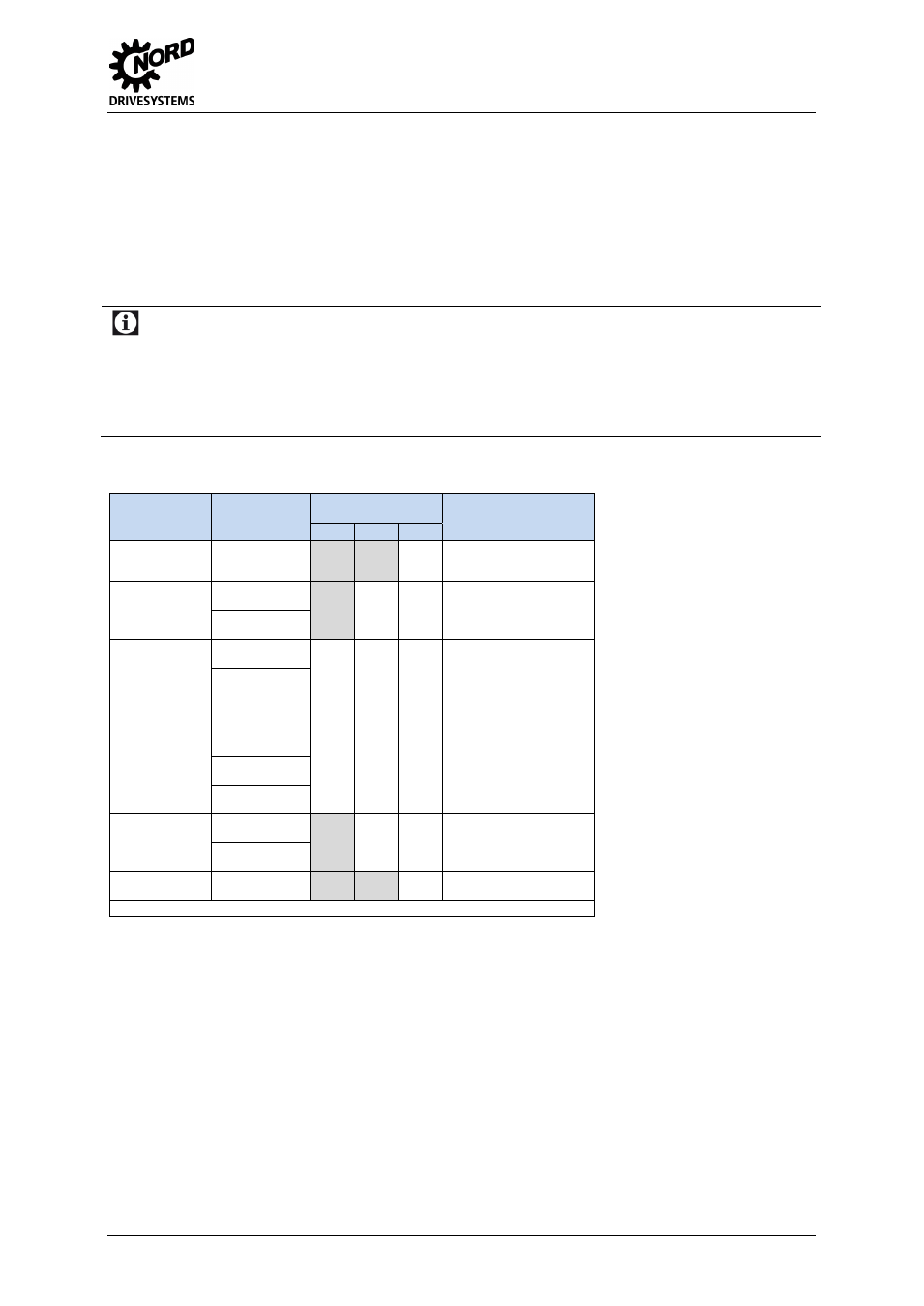
DIP switches
Function
DIP-Switch
Meaning
DIP-Switch
Combinations
Assignment
Signal
(DIP-No.)
BIT2
BIT1
BIT0
System bus
termination
resistor
S-Bus Term.
(01)
0
1
not set
setting
Addressing
system bus
S-Bus Adr. Bit 0
(02)
0
0
1
1
0
1
0
1
Adr. 20 (for FI 0 Adr. 32)*
Adr. 21 (for FI 1 Adr. 34)*
Adr. 22 (for FI 2 Adr. 36)*
Adr. 23 (for FI 3 Adr. 38)*
S-Bus Adr. Bit 1
(03)
Analog input
AIN1
Ain1 Mode Bit 0
(04)
0
0
0
1
1
0
0
1
0
0
0
1
0
0
1
0 … 10 V
2 … 10 V
-
10 … 10 V
0 … 20 mA
4 … 20 mA
Ain1 Mode Bit 1
(05)
Ain1 Mode Bit 2
(06)
Analog input
AIN2
Ain2 Mode Bit 0
(07)
0
0
0
1
1
0
0
1
0
0
0
1
0
0
1
0 … 10 V
2 … 10 V
-
10 … 10 V
0 … 20 mA
4 … 20 mA
Ain2 Mode Bit 1
(08)
Ain2 Mode Bit 2
(09)
Analog output
AOUT
Aout Mode Bit 0
(10)
0
0
1
1
0
1
0
1
0 … 10 V
2 … 10 V
0 … 20 mA
4 … 20 mA
Aout Mode Bit 1
(11)
Mode
Second - IOE
2nd IOE Mode
(12)
0
1
First SK-
…-IOE on FI
Second SK-
…-IOE on FI
* With DIP12 = ON: Address 10 … 13 instead of 20 … 23
Pos : 14 /T echnisc he I nf ormati onen/I O - Er weit er ung/ LED Anz eigen [I OE Allgemein] @ 2\ mod_1352390573890_388.doc x @ 51028 @ 6 @ 1