Io-extension – sk tu4-ioe-m12, Details of m12 connections – NORD Drivesystems TI 275281206 User Manual
Page 5
IO-Extension
– SK TU4-IOE-M12
TI 275281206 - 4912
5
Potential
Contact
Designation
Description
A
n
a
lo
g
I
O
s
1
VO 10V
10 V Reference voltage
2
VO 10V
10 V Reference voltage
3
AIN1+
Analog input 1, positive
4
AIN2+
Analog input 2, positive
5
AIN1-
Analog input 1, negative
6
AIN2-
Analog input 2, negative
7
AGND/0V
Analog Ground (internally connected to terminal 40)*
8
AGND/0V
Analog Ground (internally connected to terminal 40)*
9
AOUT
Analog Out
10
PE
PE
S
yste
m
b
u
s le
ve
l
a
n
d
d
ig
ita
l i
n
p
u
ts
11
VI 24V
Supply voltage (+24 V - in)
12
VI 24V
Supply voltage (+24 V - in)
13
VI 24V
Supply voltage (+24 V - in)
14
SYS +
System bus data cable +
15
GND/0V
Reference potential (0 V / GND)
16
SYS -
System bus data cable -
17
GND/0V
Reference potential (0 V / GND)
18
GND/0V
Reference potential (0 V / GND)
19
DIN1
Digital input 1
20
DIN3
Digital input 3
21
GND/0V
Reference potential (0 V / GND)
22
GND/0V
Reference potential (0 V / GND)
23
VI 24V
Supply voltage (+24 V - in)
24
VI 24V
Supply voltage (+24 V - in)
25
DIN2
Digital input 2
26
DIN4
Digital input 4
27
GND/0V
Reference potential (0 V / GND)
28
GND/0V
Reference potential (0 V / GND)
29
VI 24V
Supply voltage (+24 V - in)
30
VI 24V
Supply voltage (+24 V - in)
Di
g
ita
l
o
u
tp
u
ts
31
VI 24V2
Supply voltage (+24 V - in) for digital outputs
32
GND2/0V2
Reference potential (0 V / GND) of digital outputs
33
DOUT1
Digital output 1
34
DOUT2
Digital output 2
35
GND2/0V2
Reference potential (0 V / GND) of digital outputs
36
GND2/0V2
Reference potential (0 V / GND) of digital outputs
Di
a
g
n
o
stic
so
c
ke
t
RJ12 - 1
RS485_A
Data cable RS485
RJ12 - 2
RS485_B
Data cable RS485
RJ12 - 3
GND
Reference potential (GND)
RJ12 - 4
RS232_TxD
Data cable RS232
RJ12 - 5
RS232_RxD
Data cable RS232
RJ12 - 6
24 V
Supply voltage (+24 V)
* AGND/0V is internally connected to the reference voltage of the module GND/0V via a special
component. In order to prevent damage to the module or faults in the analog signals, the two
contacts must not be bridged
Potential level
1 =
2 =
3 =
4 =
Analog IOs
System bus + DIN
DOUT
Diagnosis
Pos : 11 /T echnisc he I nf ormati onen/I O - Er weit er ung/D et ail M12-Ansc hlüsse [ SK TU 4- xxx-M 12] @ 2\ mod_1353315471763_388.doc x @ 51301 @ @ 1
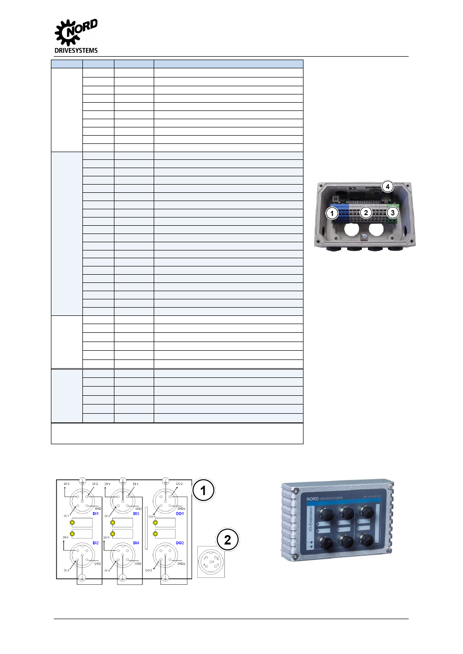
Details of M12 connections
1 =
2 =
Wiring with M12 plug connectors
Details of pin numbering